Adiüsfmerifs – Sears 113.24611 User Manual
Page 17
Attention! The text in this document has been recognized automatically. To view the original document, you can use the "Original mode".
adiüsfmerifs
WARNilMG: FOR YOUR OWN SAFETY TURN SWITCH
"OFF" AND REMOVE PLUG FROM POWER SOURCE
OUTLET BEFORE MAKING ANY ADJUSTMENTS.
DEPTH SCALE
When the quill is in the UPPERMOST position, the top
SURFACE OF THE FEED STOP POINTER should be in
line with "0" graduation on the DEPTH SCALE.
If it is not . . . LOOSEN both mounting screws and
reposition the scale.
FEED STOP
POINTER
MOUNTING
SCREWS
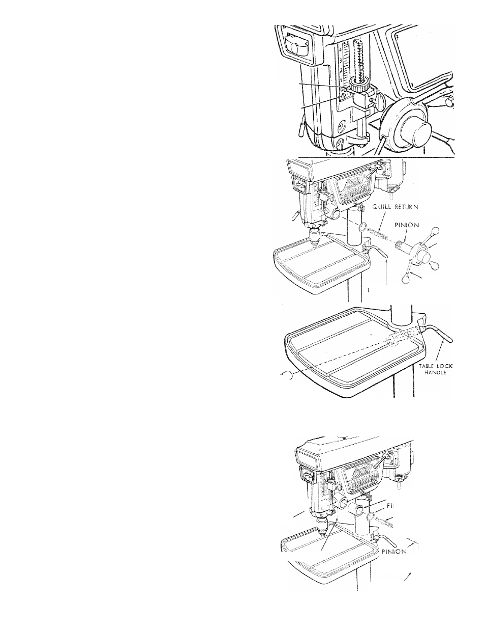
QUILL
RETURN SPRING
If the quill does not return to its UPPERMOST position
when the quill lock is UNLOCKED . . . or if the return
action is SLUGGISH ... the SPRING TENSION must be
increased.
1
. Move DEPTH POINTER to uppermost position and
lock it in place.
2. Lock the quill in the uppermost position.
3. GRASP the HUB . . . pull it straight out until it is free
to turn.
4. Rotate hub TOWARD you about 1/4 turn and PUSH it
back in place. This will WIND UP the spring.
5. Unlock quill . . . check tension . . . if more is required,
repeat steps 2, 3, 4, and 5.
TABLE AND HEAD LOCK HANDLES
The lock
handles
can be
adjusted to make them more
convenient
to operate.
1. Make sure the support collar is locked in position below
the table or the head.
2
. Unscrew the lock handle and push the barrel lock out
of the hole.
3. Rotate the barrel lock 180°, replace it in the hole and
screw in the handle.
NOTE:
The HEADLOCK HANDLE is located on the LEFT
side of the head.
SPRING
HUB
ABLE LOCK
HANDLE
FEED
HANDLE
IT,
\
BARREL LOCK
BELT TENSION
Refer to section "Getting To Know Your Drill Press"
BELT TENSIONING ROD.
QUILL
BEARING ADJUSTMENT
The front of the head is "Split" which permits an
adjustment to be made as the quill and the quill bearing
surfaces inside of the head become worn after an extended
period of use. The front of the head can be SQUEEZED
together or SPREAD apart by adjusting three screws.
1. TIGHTEN quill lock handle.
2.
LOOSEN setscrew "A" using a 5/32 in. setscrew
wrench.
3.
Rotating the eccentric BUSHING "B" in either
direction will move the pinion shaft TOWARD or
AWAY from the quill.
With a large pair of pliers, rotate bushing so that pinion
shaft moves AWAY from quill.
4. LOOSEN quill lock handle.
QUILL
LOCK
HANDLE
ECCENTRIC BUSHING
3ER WASHER
SPLIT
SET SCREW "A"
FEED RETURN
SPRING '
'
,'/■—'\ VT-/
SHAFT
U.
i'y /'s
H U 8
ASSERABt'-
I FEED HAMUlX
17