Sears 300 User Manual
Page 9
Attention! The text in this document has been recognized automatically. To view the original document, you can use the "Original mode".
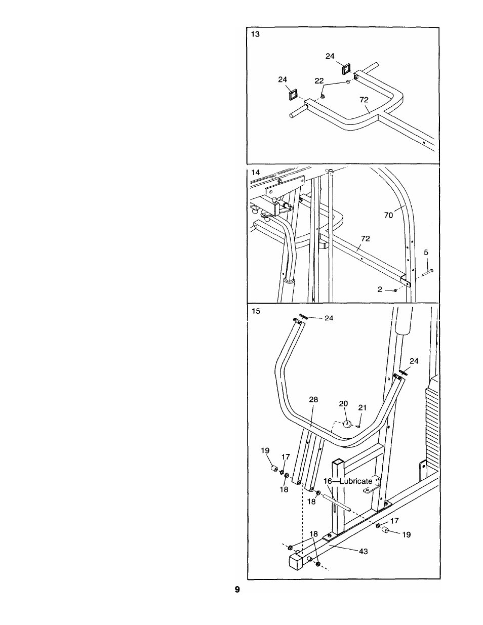
13. Tap two 1 3/4” Inner Caps (24) into the Squat Arm
(72).
Tap two 1” Round Caps (22) into the Squat Arm
(72).
14. rti'.cicri tiie St
4
uai A./vi (72) to iriG \'KR Uprigt.i
(70) with a 3/8” x 3 1/4” Bolt (5) and a 3/8” Jam
Nut (2).
Do not overtighten the Jam Nut; the
Squat Arm must pivot freely.
15. Tap two 1 3/4" X 1 3/4” Inner Caps (24) into the
upper end of the Press Arm (28).
Attach a Rubber Bumper (20) to the Press Arm
(28) with a #8
X
1/2” Tap Screw (21).
Make sure that there are two 3/4” Flange
Bushings (18) in the indicated holes in the Base
(43). Make sure that there are two 3/4” Flange
Bushings (18) in the indicated holes in the Press
Arm (28).
Appiy lubricant to the 3/4” x 8 1/2” Axle (16). Align
the bottom of the Press Arm (28) with the Base
(43). Slide the Axie into the Press Arm and Base.
Tap a 3/4” Retainer (17) and a 3/4” Retainer Cap
(19) onto each end of the Axle.
Note: The teeth
on the Retainers must bend toward the
Retainer Cap.