Sears 300 User Manual
Page 13
Attention! The text in this document has been recognized automatically. To view the original document, you can use the "Original mode".
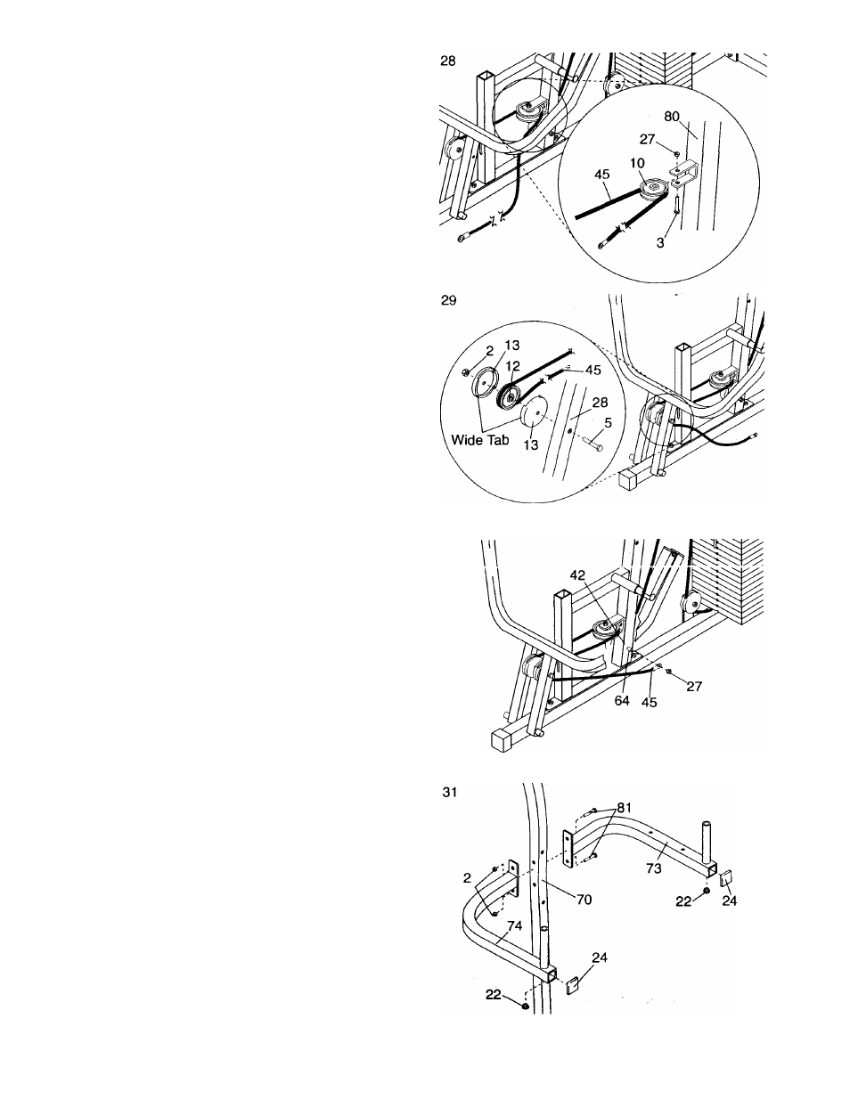
28. Route the Long Cable (45) around the 3 1/2” “V”-
Pulley (10). Attach the “V”-Pulley to the bracket
on the Frame (80) with a 3/8” x 2 1/2” Bolt (3) and
a 3/8” Nylon Locknut (27).
nv-»Ljt
3
ihe uOny
(‘
t
O) doVwIi c.iCUl'iO c* O
i /
Pulley (12). Attach the Pulley and two Pulley
Covers (13) to the indicated side of the Press
Arm (28) with a 3/8” x 3 1/4” Bolt (5) and a 3/8”
Jam Nut (2).
Make sure that the Pulley Covers
are turned so the wide tabs are positioned as
shown.
30. Remove the indicated 3/8” Nylon Locknut (27).
Attach the end of the Long Cable (45) to the 3/8”
X 4” Bolt (64) in the Frame (80) with the 3/8”
Nylon Locknut (27).
Do not overtighten the
Nylon Locknut, the Cable must pivot freeiy.
iMPORTANT: Before continuing, refer to the
CABLE DIAGRAMS on pages 22 and 23, and
make sure that the Long Cable (45) and Short
Cable (not shown) are correctly routed. In
addition, refer to TROUBLE-SHOOTING AND
MAINTENANCE on page 21, and adjust the
Cables as described.
31. Tap a 1 3/4” x 1 3/4” Inner Cap (24) into each of
the VKR Arms (73, 74). Tap a 1” Round Cap (22)
into each of the handles on the VKR Arms.
Attach the Left and Right VKR Arms (73, 74) to
the VKR Upright (70) with two 3/8” x 2 3/4” Bolts
(81) and two 3/8” Jam Nuts (2).
30
13