Sears 300 User Manual
Page 12
Attention! The text in this document has been recognized automatically. To view the original document, you can use the "Original mode".
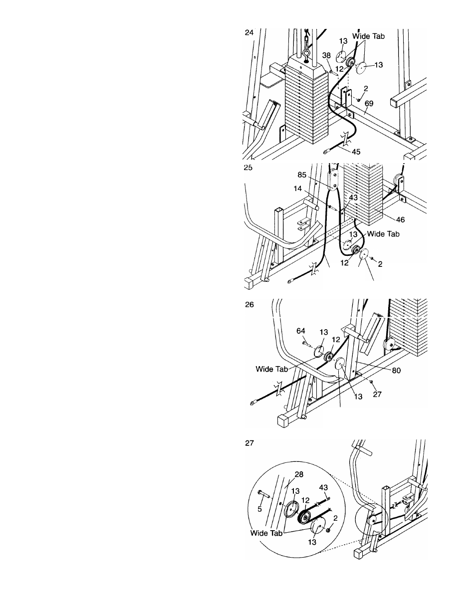
24. Route the Long Cable (45) under a 3 1/2” Pulley
(12). Attach the Pulley and two Pulley Covers (13)
to the “U” bracket on the Stabilizer (69) with the
3/8”
X
2” Bolt (38) and a 3/8” Jam Nut (2).
Make
sure that the Pulley Covers are turned so the
wide tabs are positioned as shown.
25. Feed the Long Cable (45) under the Wsights (46).
Route the Long Cable (45) under a 3 1/2” Pulley
(12). Attach the Pulley and two Pulley Covers (13)
to the bracket on the Base (43) with a 3/8” x 1 3/4”
Bolt (14) and a 3/8” Jam Nut (2).
Make sure that
the Pulley Covers are turned so the wide tabs
are positioned as shown.
Feed the Long Cable (45) over the lower 4 1/2”
Pulley (85).
26. Route the Long Cable (45) under a 3 1/2” Pulley
(12). Attach the Pulley and two Pulley Covers (13)
4.... 41--- .
x
4i_______________________
/nr\\
...uu 4i_____________
i i i c i i i u i C a i c u O l u c i i 1 C I I a i l 1 C
v v i u t u i c
3/8”
X
4” Bolt (64) and a 3/8” Nylon Locknut (27).
Make sure that the Pulley Covers are turned
so the wide tabs are positioned as shown.
27. Route the Long Cable (45) up around a 3 1/2”
Pulley (12). Attach the Pulley and two Pulley
Covers (13) to the indicated side of the Press
Arm (28) with a 3/8” x 3 1/4” Bolt (5) and a 3/8”
Jam Nut (2).
Make sure that the Puiiey Covers
are turned so the wide tabs are positioned as
shown.
45
13
Wide Tab
Wide Tab
12