Sears 113.243311 User Manual
Page 19
Attention! The text in this document has been recognized automatically. To view the original document, you can use the "Original mode".
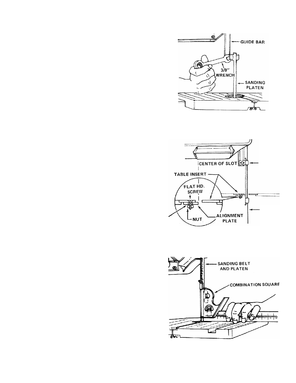
6. Attach the sanding platen to the guide bar with the
same screw that held the upper blade guide assembly.
Do not tighten the screw at this time.
On the smooth side of the sanding belt, you will find a
"directional arrow". The belt must run in the direction
of this arrow so that the splice does not come apart.
7. Place the belt on the wheels and tighten the tension
knob until the pointer points to SAND. Rotate the
upper wheel by hand a few times to make sure that the
belt is tracking properly and is not rubbing the guides.
8. Loosen the guide bar lock screw and lower the end of
the sanding platen below the table.
Locate among the
flat head machine
and lockwasher.
loose parts, the alignment plate, a
screw 6-32 X 7/16", a small hex nut
iO. Attach the alignment plate to the insert so that the end
of the alignment plate is in the center of the slot in the
insert. Place the insert in the opening in the table.
SANDING
PLATEN
LOCKWASHER
SANDING
BELT
11. Hold a square on the table against the sanding belt and
platen.
12. Tighten the hex. head screw which holds the platen to
the guide bar.
13. Replace the cover.
WARNING; FOR YOUR OWN SAFETY, DO NOT SAND
IRON OR STEEL BECAUSE THE SPARKS COULD IG
NITE THE SAWDUST INSIDE YOUR BAND SAW.
19