Carrier 19QA User Manual
Page 6
Attention! The text in this document has been recognized automatically. To view the original document, you can use the "Original mode".
NO.
ITEM
NO.
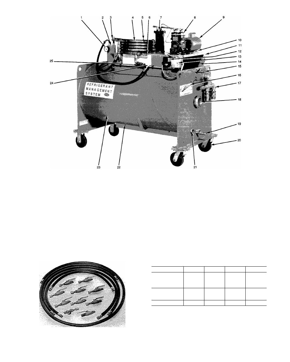
1
— Pressure Gage
12 —
2
— Purge Separator Assembly
3
— Refrigerant (Vapor) In
13 —
4
— Tube-in-Tube Condenser
14 —
5
— Filter Drier
Vi
SAE Flare (Hidden)
6
— Refrigerant (Liquid) Out
7
— Oil Separator
8
— Pump
9
—
Pump
Motor
10
— Heater High-Pressure
Cutout Switch (Hidden)
11
— Heater ON/OFF Switch (Hidden)
15 —
ITEM
Pump High-Pressure
Cutout Switch
Pump ON/OFF Switch
Storage Area
Components Included:
Refrigerant Hose, 3 ft
Refrigerant Hose, 6 ft (2)
Refrigerant Hose, 12 ft
Valve With Coupler (8)
Chiller Vapor Valve
Liquid Indicator With Coupler
Vapor Valve
NO.
ITEM
16
— Refrigerant Capacity Chart
17
— Relief Valve Assembly
18
— Level Gage
19
— Liquid Valve
20
— Accessory Casters
(Available On All Tank Sizes)
21
— Water Separation Sight Glass
22
— Heater With Cover
23
— Storage Tank
24
— Water
In
25
— Water Out
Fig. 4 — 19QA Refrigerant Management System Components
Table 3 — Electrical Data
Fig. 5 — Interconnecting Refrigerant Hoses,
Valves, and Fittings
VOLTS-PH-HZ
115-1-50
115-1-60
230-1-50
230-1-60
PUMP MOTOR
Hp
3/4
3/4
3/4
3/4
Amps
9.6
8.6
4.8
4.3
MCA
10
10
5
5
HEATER
Amps
12
12
6
6
MCA
12
12
11
11
MOCP
15*
15*
15
15
LEGEND
MCA — Minimum Circuit Amps
MOCP — Maximum Overcurrent Protection (Amps)
*Two circuits required for simultaneous operation.
NOTE: Use time-delay fuses.