Carrier 19QA User Manual
Page 12
Attention! The text in this document has been recognized automatically. To view the original document, you can use the "Original mode".
Purge Separator Assembly
— A purge separator
assembly is used to remove noncondensable gases that may
be mixed with the refrigerant being recovered. See Fig. 4.
If vapor is being recovered from a leaking chiller, air will
enter the machine. The air will mix with the refrigerant gas
and collect in the storage tank. The air will raise the pres
sure of the storage tank until the pressure reaches 10 psig
(69 kPa). At this point, the high pressure cutout switch will
turn off the pump. To avoid this situation, a purge separa
tor assembly is factory installed. See Fig. 8.
During the vapor recovery process, the pressure in the
storage tank should not be higher than the corresponding
pressure/temperature relationship for a given refrigerant, based
on ambient conditions. If the room temperature is approx
imately 75 F (24 C) and CFC-11 is being recovered, the
pressure in the storage tank should be approximately 0 psig
(0 kPag). If the pressure is higher than 0 psig (0 kPag), a
noncondensable gas is present in the storage tank. See
Table 5.
A pressure gage is mounted on top of the purge separator
assembly. When the pressure reaches 8 psig (55 kPag) and
the pressure/temperature relationship shows this as exces
sive, the purge valve on top of the purge separator assem
bly should be opened to remove the noncondensable gas.
See Fig. 4. Based on the ambient temperature, the purge
separator assembly should be operated until the saturated
pressure is achieved. If the ambient temperature is 75 F
(24 C), the purge valve should be opened until the storage
tank pressure reaches 0 psig (0 kPa).
Oil Separation
— The refrigerant management system
separates oil from refrigerant through distillation. The re
frigerant can be transferred from the chiller to the storage
tank and then distilled back to the chiller or another storage
tank.
Connect the 3-ft refrigerant hose from the storage tank
vapor valve to the pump suction service valve. See Fig. 13.
Copper tubing is factory installed from the pump to the oil
separator. Connect the 6-ft refrigerant hose from the oil sep
arator discharge connection to the top connection on the
tube-in-tube condenser. Connect the 12-ft refrigerant hose
with the liquid indicator to the refrigerant outlet connection
on the condenser and to the chiller charging valve or an
other storage tank. Provide water at approximately 2 gpm
(.012 L/s) and a maximum temperature of 70 F (21 C) to
the tube-in-tube condenser using suitable water hoses. Turn
on the pump and heater using the toggle switches provided.
If the distilled refrigerant is being returned to the chiller,
run cool water through the evaporator heat exchanger. Ap
proximately 1.2 lb per minute (.54 kg per minute) of CFC-11
can be distilled per hour. When liquid refrigerant is no longer
seen in the liquid indicator, the distillation process is
complete.
After the distillation process is complete, the oil remain
ing in the bottom of the storage tank should be drained us
ing the liquid valve on the storage tank. After the oil is
drained, the tank can be wiped clean by opening the access
cover located on the opposite end of the level gage.
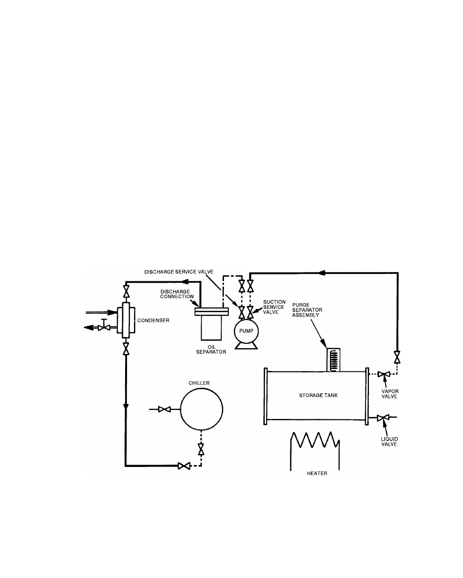
WATER
CONNECTIONS
Refrigerant Hose
Water Hose
Direct Coupled Connection
Factory-lnstailed Copper Tubing
Fig. 13 — Oil Separation Connections
12