Carrier 50NQ User Manual
Page 13
Attention! The text in this document has been recognized automatically. To view the original document, you can use the "Original mode".
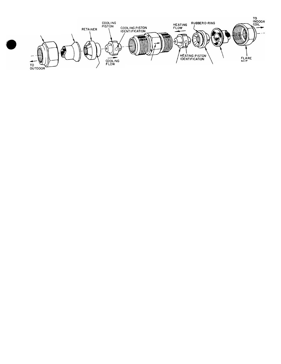
FLARE
NUT
STRAINER
COIL
RUBBER 0-RING
STAMPED ARROW ON
COUPLING BODY
(TOWARD INDOOR COIL)
STRAINER
RETAINER
A87292
Fig. 11—Metering Device (Duai-Piston) Components
Inspect the fan blades for cracks or bends each year. Ensure
that blades clear the motor by no more than 1/4 in. The fan
blade hub should be flush with end of motor shaft. If the
blade assembly has slipped down the motor shaft, adjust the
fan position on the motor shaft by loosening the setscrew(s),
then moving the blade assembly up. Be sure that the set-
screw(s) is on the flat(s) of the motor shaft before tightening.
ELECTRICAL CONTROLS AND WIRING
Inspect and check the electrical controls and wiring annu
ally. Be sure to turn off the electrical power to the unit.
Remove the control, blower, and compressor compartment
access panels to locate all the electrical controls and wiring.
Check all electrical connections for tightness. Tighten all
screw connections. If any smoky or burned connections are
noticed: disassemble the connection, clean all the parts,
restrip the wire end, and reassemble the connection properly
and securely.
After inspecting the electrical controls and wiring, replace
all the panels. Start the unit and observe at least one com
plete heating cycle and one complete cooling cycle to ensure
proper operation. If discrepancies are observed in either or
both operating cycles, or if a suspected malfunction has
occurred, check each electrical component with the proper
electrical instrumentation. Refer to the unit wiring label
when making these checkouts.
NOTE:
Refer to the heating and/or cooling sequence of oper
ation in this publication as an aid in determining proper con
trol operation.
REFRIGERANT CIRCUIT
Inspect
Eill
refrigerant tubing connections and the unit base
for oil accumulations annually. Detecting oil generally indi
cates a refrigerant leak.
If oil is detected or if low cooling performance is suspected,
leak-test all refrigerant tubing; using an electronic leak-
detector, halide torch or liquid-soap solution. If a refrigerant
leak is detected, see “Refrigerant Leaks” in this
publication.
If no refrigerant leaks are found and low cooling perfor
mance is suspected, refer to “Checking Charge” and unit
rating plate.
INDOOR AIRFLOW
The heating and/or cooling airflow does not require checking
unless improper performance is suspected. If a problem
exists, be sure that all supply- and return-air grilles are open
and free from obstructions, and that the air filter is clean.
When necessary, refer to “Indoor Airflow and Airflow
Adjustments,” page 10 of this publication to check the sys
tem airflow.
METERING DEVICE SERVICING
See Fig. 11 for metering device components. The pistons
have a refrigerant metering orifice through them. The
retainer forms a sealing surface for liquid line flare connec
tion. To check, clean or replace piston:
1. Shut off power to unit.
2. Remove refrigerant from unit using approved refriger
ant removal methods.
3. Remove liquid line flare connections from metering
device.
4. Note position of arrow on metering device body with
respect to unit.
5. Pull retainers out of body. Be careful not to scratch
flare sealing surfaces. If retainers do not pull out eas
ily, carefully use locking pliers to remove retainers.
Replace scratched or damaged reteuners.
Slide pistons out by inserting a small soft wire through
metering hole (18-gauge thermostat wire). See that
metering hole, seeding surface around piston cones and
fluted portion of pistons are not damaged.
Chart on unit access panel illustrates proper arrange
ment and size of pistons.
Clean pistons refrigerant metering orifice.
Replacement retainer 0-ring Part No. is 99CC501052.
6
.
LIQUID LINE STRAINER
The Liquid Line Strainers (to protect metering device), are
made of wire mesh and are located in the liquid line on both
sides of the metering device. Strainers are pressed into the
line. Remove strainers by threading a No. 10 sheet metal
screw into strainers and pulling the screw with pliers.
13