Cooling capacities - 30gb060, Performance data (cont), Legend – Carrier 30GB060 User Manual
Page 9
Attention! The text in this document has been recognized automatically. To view the original document, you can use the "Original mode".
Performance data (cont)
COOLING CAPACITIES - 30GB060
CONDENSER ENTERING AIR TEMPERATURE (F)
LCWT
85
90
95
Cap.
SDT
kW
Cooler
Cap.
SDT
kW
Cooler
Cap.
SDT
kW
Cooler
Flow
Rate
PD
Flow
Rate
PD
Flow
Rate
PD
40
58.5
113.2
63.7
139 9
124
56 7
1177
65.4
135.6
11 7
55 0
122.1
67.0
131 5
11.0
42
60 9
114.3
65.1
145.7
13.4
59.1
118.7
66.9
141.4
12.6
57.3
123 2
68.6
137.1
11.9
44
63 4
115.3
66.5
151.7
144
61.5
119.8
68.4
147.2
13.6
59.7
124.2
70.1
142 9
129
45
64.6
115.9
67.2
154.7
15 0
62 7
120 3
69.1
150.2
14.2
60.9
124
8
70.9
145
8
13 4
46
65.9
116.5
67.9
157.8
15
6
64.0
120 9
69 9
153 2
14.7
62.1
125.3
71 7
148.7
13.9
48
68.4
1176
69.4
164 0
16.8
66.5
122.0
71.4
159 4
15.9
64
6
126.5
73.3
154
8
15.0
50
71.1
118.8
70.8
170.4
18.0
69 1
123.2
72 9
165.7
17 1
67.1
127
6
74.9
161.0
16
2
55
77.9
121.8
74
6
187.0
21.5
75.8
126
2
76 9
182.0
20 5
73.8
130.6
79.1
177 0
19.4
60
85.2
125.1
78.5
204
6
25.6
82 9
129.4
81.0
199 3
24.3
80.7
133
8
83 4
193.9
23.1
CONDENSER ENTERING AIR TEMPERATURE (F)
LCWT
105
115
Cooler
Cooler
Cap.
SDT
kW
Flow
Rate
PD
Cap.
SDT
kW
Flow
Rate
PD
40
51.6
131.1
70.0
123 3
9.7
48.1
140.0
72
6
114.9
8.5
42
53.8
132.1
71.7
128 7
10.5
50 2
141.0
74 4
120.1
92
44
56.1
133 2
73 4
134 2
11 4
52.4
142.0
76.3
125 4
10
0
45
57.2
133.7
74.3
137.0
11 9
53 5
142.5
77.3
128
1
10.5
46
58.4
134 2
75.1
139.9
124
54
6
143.1
78.2
130
8
10.9
48
60.8
135.3
76 9
145.7
13.4
56 9
144.1
80.1
136.3
11
8
50
63 2
136.4
78.7
151
6
144
59 2
145.2
82.1
142.0
12.7
55
69 5
139.3
83.2
166
8
17.3
—
—
—
—
—
60
76.2
142.4
87.8
183.1
20.7
—
—
—
—
—
Cap.
Flow Rate
kW
LCWT
PD
SDT
NOTES:
1
2
LEGEND
Cooling Capacity Tons of Refrigeration
U S Gpm
Compressor Power input
Leaving Chilied Water Temperature (F)
Pressure Drop (Ft of Water)
Compressor Saturated Discharge Temperature (F)
Ratings appiy to units with electronic or thermai expansion vaives.
Aii ratings are based on.
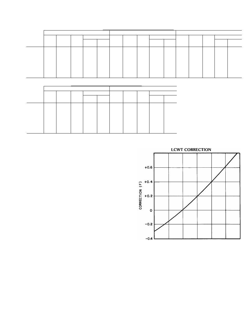
a. A cooler chilled water temperature rise of 10° F. When greater
accuracy is desired, correct design LCWT, before entering
rating tabies, by reference to the LCWT correction curve.
b. A fouling factor of 0.0005 in the cooler,
c Refrigerant 22.
3
When a corrected LCWT is used, cooler pressure drop must also
be corrected for new LCWT :
a Enter rating tabie for corrected LCWT By interpolation,
determine corrected capacity (tons) and power input (kW) to
compressor at its rated voltage,
b Calculate corrected flow rate through the cooler.
24
X
capacity in tons
“
X
X
. — “ U S Qpm
temperature rise F
c.
Enter cooier pressure drop curve at corrected fiow rate and
read pressure drop
4. When chiiled water temperature rise is iess than 5°F, high fiow
rate will normally be accompanied by an excessive pressure drop.
In such cases, contact your Carrier representative for speciai
selection of a cooler with wider baffle spacing.
5
lO
i5
20
COOLER CHILLED WATER TEMPERATURE RISE (F)
Above 10F, ADD correction to design LCWT, below 10 F, SUBTRACT