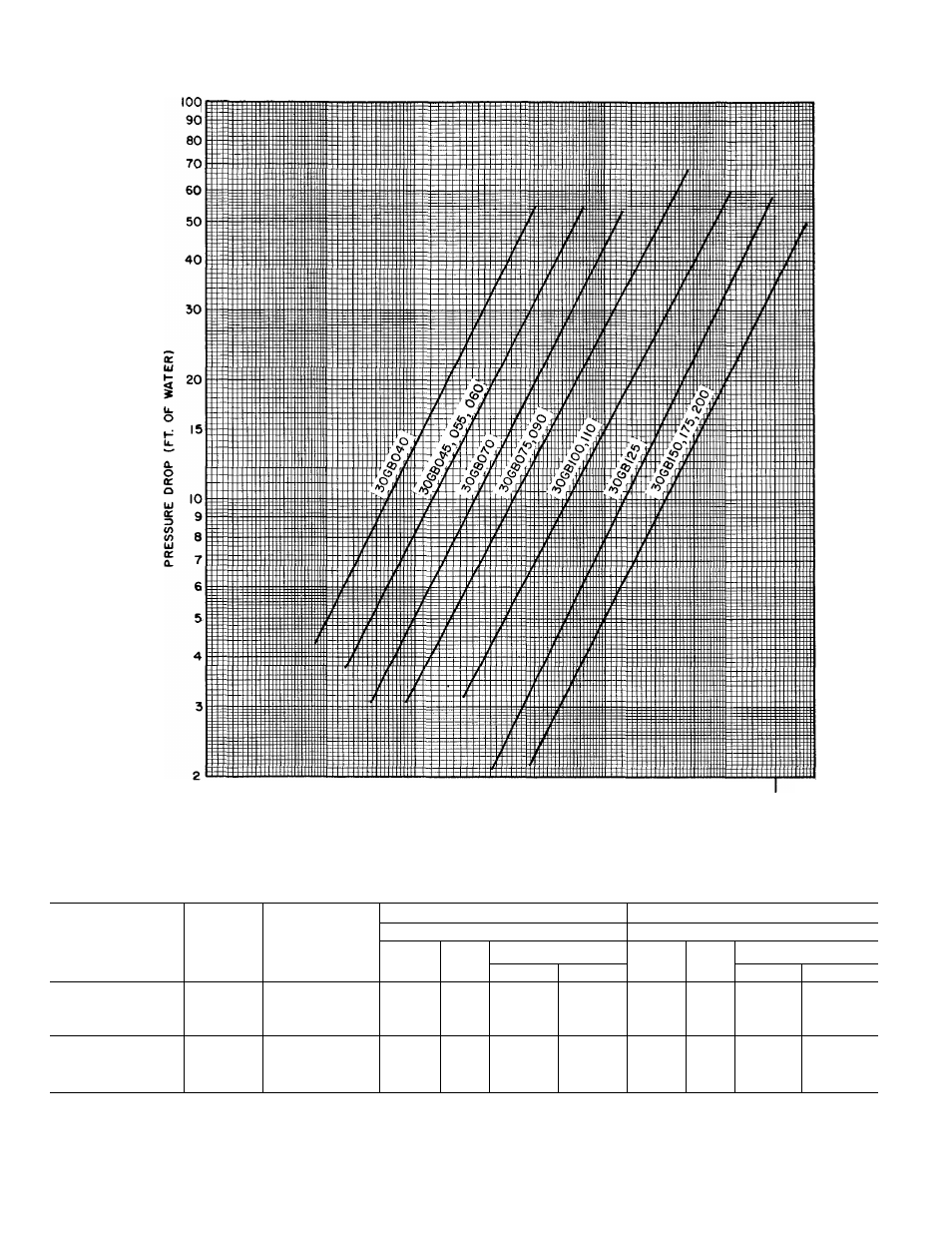
Performance data (cont), I —i, Total cooler pressure drop (water side) – Carrier 30GB060 User Manual
Page 8: Capacity control steps
Attention! The text in this document has been recognized automatically. To view the original document, you can use the "Original mode".
Performance data (cont)
300-
270
240-
210
180-
ISO
120
-
90-
75-
•5
60-1
a.
Ko
UJ
5
(f>
UJ
a.
45-
30-
27
24
21
18-
15-
12
-
9-
TOTAL COOLER PRESSURE DROP (Water Side)
80 90100
600 TOO
1000
COOLER WATER FLOW (6PM)
800
-T—
3
7
10
15
20
COOLER WATER FLOW (L/S)
30
—I-----1—I
40
50 60
CAPACITY CONTROL STEPS
UNIT 30GB060
CONTROL
STEPS
%
DISPLACEMENT
(Approximate)
LOADING SEQUENCE A (Note 1)
LOADING SEQUENCE B (Note 1)
Operating
Operating
No.
of
Compr
No.
of
Cyl
Compressor No.
No.
of
Compr
No.
of
Cyl
Compressor No.
Circuit 1
Circuit 2
Circuit 1
Circuit 2
1
29
1
4
1
*
—
—
__
__
Standard
2
43
1
6
1
—
—
—
—
—
(One Unloader)
3
72
2
10
1
*
2
—
—
—
—
4
100.0
2
12
1
2
—
—
—
—
Accessory Unloader
Added to
Compressor No. 2
1
2
3
4
38
66
85
100
1
2
2
2
4
8
10
12
1
*
1
*
1
*
1
2
*
2
2
1
2
2
2
4
8
10
12
1
*
1
1
2
*
2
*
2
*
2
‘Compressor unloaded.
NOTES:
1. The microprocessor has a random number generator that selects
loading sequence A or B, which in turn determines the com
pressor circuit that is energized first. This evens out operating
hours on each circuit over an extended period of time
If unit operation is anticipated with system load below minimum
unloaded capacity of chiiler:
a. Consider using 2 smaller units in place of larger unit.
b. Increase
water loop volume
to ensure adequate run time (see
Application Data).