Fig. 9 — machine hot surfaces – Carrier 16JB User Manual
Page 8
Attention! The text in this document has been recognized automatically. To view the original document, you can use the "Original mode".
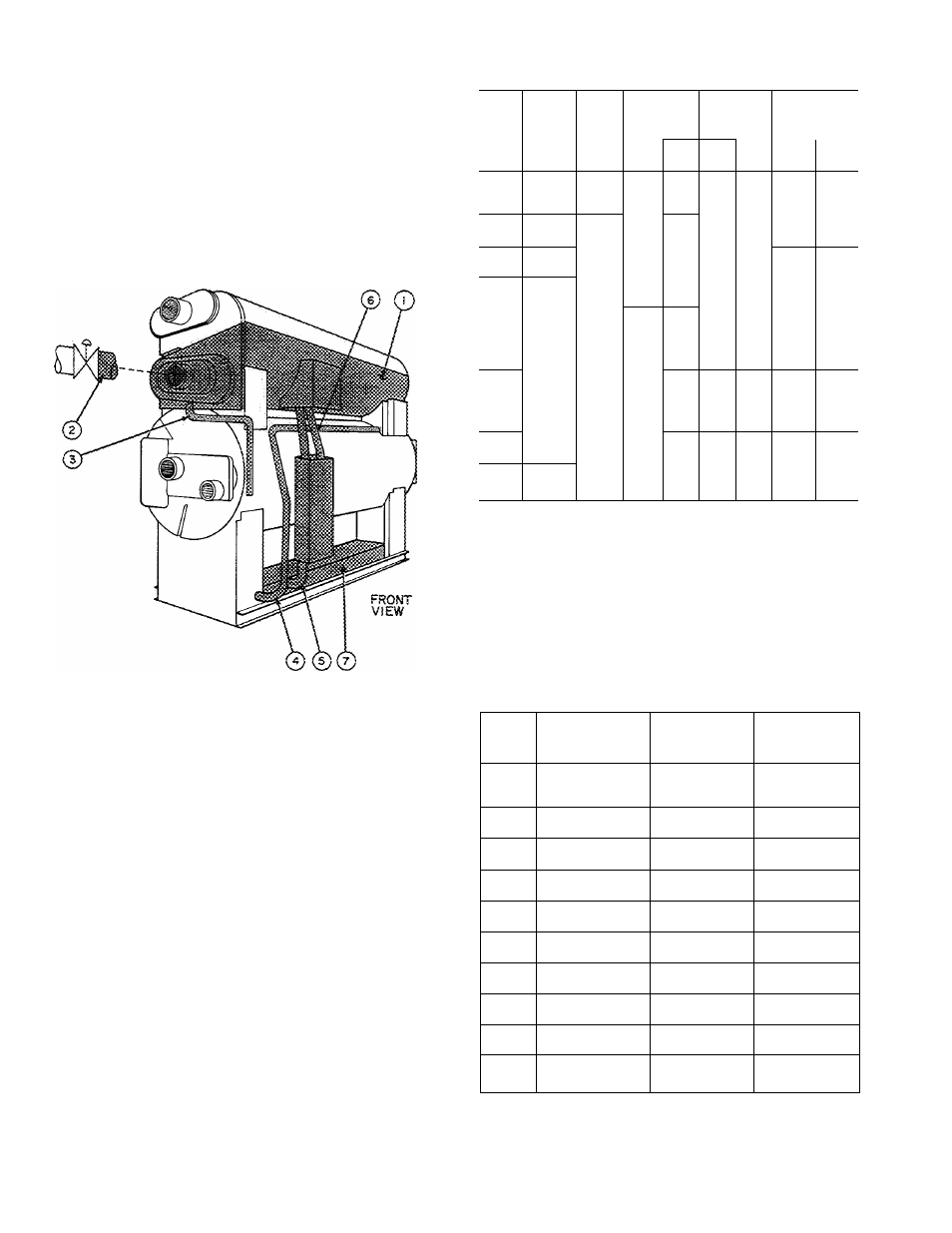
The generator shell and some of the machine
piping will become hot during operation. If insula
tion is to be used as a safety precaution, or to
reduce ambient temperature in the machine room,
we recommend insulating the surfaces shown in
Fig. 9. Hot-surface dimensions are given in Table 3.
Generator insulation can be either blanket-type
or low-pressure boiler insulation. Insulation used
for piping is generally standard low-pressure steam
pipe insulation.
Table 3 — Insulation For Hot Surfaces*
HOT SURFACES THAT
CAN BE INSULATED
LEGEND
1 — Generator Shell (refer to Table 4 for sq ft surface area)
2 — Steam Supply Line
3 — Condensate Line
4 — Weak Solution Line (to generator)
5 — Strong Solution Line (from generator)
6 — Generator Overfiow Tube (only hot during abnormal
conditions)
7 — Heat Exchanger
Fig. 9 — Machine Hot Surfaces
isolation
— 16JB machines are not in themselves a
major source of vibration ; and isolation equipment
is not supplied with the machine unless requested
on the order. It is possible, however, for a machine
to receive and transmit vibrations from other
sources that are imperfectly isolated such as
condensing water pumps, chilled water pumps, or
other piping. Isolation packages are available from
a number of manufacturers. Specifications for
Carrier machines are given in Table 4.
UNIT
16JB
GENt
SHELL
HT
EXCH
STRONG
SOL LINE
WEAK
SOL LINE
GEN
OVERFLOW
(GO) TUBE
(ft 2)
(ft 2)
Lgth
(ft)
Size
(in.)
Lgth
(ft)
Size
(in.)
Lgth
(ft)
Size
(in.)
010
012
014
62
40
7
3
20
V/2
1 1
3
018
021
67
45
7
3
21
2
12
4
024
028
72
50
8
4
22
2
13
4
032
036
77
55
9
4
23
2'/2
15
4
041
047
82
60
10
4
24
3
16
4
054
057
98
55
8
4
22
3
10
4
061
068
98
60
10
4
24
3
12
4
077
084
152
102
16
4
44
2
3
4
097
107
184
no
18
4
47
3
4
4
115
124
184
1 18
20
4
49
3
4
4
•Refer to Fig. 10 for location of hot surfaces.
fl nciudes outiet box and ends
GEN
—Generator
HT EXCH
— Heat Exchanger
Table 4 — Isolation Pad and Soleplate
Specifications
UNIT
16JB
NO. (EACH)
OF PADS AND
SOLEPLATES
PAD
DIMENSIONS
(in.)
SOLEPLATE
DIMENSIONS
(in.)
010
012
014
4
9 X
6
X
%
10 X
7
X
V
2
018
021
4
9 X 10 X
%
10 X 11
X V
2
024
028
4
9 X 12 X Vs
10
X 13 X
%
032
036
4
9 X 14 X %
10 X 1 5 X
(4
041
047
4
9 X 18 X %
10 X 19 X
%
054
057
4
12 X 18 X Vs
13 X 19 X
%
061
068
4
14 X 18 X %
15 X 19 X h
077
084
6
12 X 18 X
%
13 X 19 X
%
097
107
6
15 X 18 X Vs
16 X 19 X
%
115
124
6
16 X 18 X %
17 X 19 X
‘/2
NOTE:
Higher isolation efficiencies may be obtained with double-layer
pads. Double-layer pads, factory-fused together, are available from
various manufacturers. If two single-layer pads are used, a metal
divider equal to pad dimensions should be inserted between iayers.