Table 5 — chargemaster charging chart – Carrier 50WQ User Manual
Page 9
Attention! The text in this document has been recognized automatically. To view the original document, you can use the "Original mode".
#
#
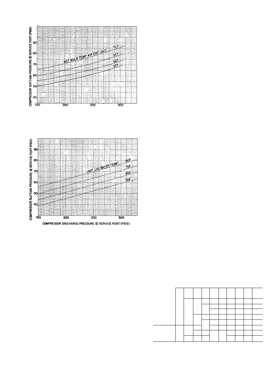
COMPRESSOR DISCHARGE PRESSURE® SERVICE PORT (PSIG)
Fig. 16 — 50WQ042 Cooling Cycle
Charging Chart (R-22)
Fig. 17 — 50WQ042 Heating Cycle Operation
Check Chart (R-22)
6. Read evaporator temperature at red needle posi
tion on Chargemaster temperature gage and
suction line temperature at black needle position.
CAUTION; i>o not read evaporator tem
perature witfe Chargernaster valve open.
7. Enter 50WQ Chargemaster Charging Chart,
Table 5, at unit leaving water temperature (step 5)
and evaporator temperature (step 6). (Do not use
standard charging chart on cover of Charge-
master device.) Find the suction line temperature
required for correct system charge. If actual
suction line temperature (step 6) is higher than
table value, the system is undercharged. If
suction line temperature is lower than table
value, the system is overcharged.
Example: At leaving water temperature of 93 F
and evaporator temperature of 41 F, the system is
correctly charged at 50 F ( ± 2 F) suction line
temperature.
8. Add charge by slowly opening Chargemaster
valve. If necessary, reduce charge by bleeding at
liquid line Schrader valve. Check outdoor air and
evaporator temperature during procedure. If
they change, refer back to Chargemaster
Charging Chart for new value.
Correct use of Chargemaster device ensures that
an optimum refrigerant charge is in system when
conditions and system components are normal.
However, the device does not solve or fix system
abnormalities. It indicates correct charge for condi
tion of system. It does not make corrections for dirty
filters, slow fans, or other abnormal conditions.
This charging device ensures that a correct relation
ship exists between leaving water temperature, evap
orator temperature, and suction line temperature on
a specific system.
CHARGEMASTER® DEVICE OPERATION —
Operate unit 10 minutes before using device. Ensure
unit indoor fan section access panel is in place for
proper Chargemaster operation.
1. Tape Chargemaster feeler bulb to unit suction
line. Insulate bulb. Ensure suction line is clean
for good contact with bulb.
2. Connect refrigerant drum to Chargemaster inlet
port with drum in position for vapor charging.
3. Connect Chargemaster outlet port (loosely) to
unit suction line Schrader valve.
4. Crack valves on refrigerant drum and Charge-
master device to purge lines from drum to suction
line Schrader valve. After purging lines, close
valve on Chargemaster device only. Tighten
Chargemaster
connection
at
suction
line
Schrader valve.
5. Measure unit leaving water temperature.
Table 5 — Chargemaster Charging Chart
UNIT
LEAVING
WATER
TEMP
(F)
3o]
41
44
EVAPORATOR TEMP (F)
33_I
ss
J
m
47
50
53 56
Suction Line Temperature (F)
" _
75
46
45*
49^
47
51
50
54
53
57
55
59
58
61
60
64
—
81
46
49
51
54
56
57
63
87
48
50
52
54
56
62
65
93
46
48
50
53
55
57
61
99
47
49
51
54
56
61
64
105
45
47
50
53
56
60
63
112
46
49
53
55
59
62
117
45
47
52
55
57
61
123
46
50
53
55
56
*Saturated evaporator temperature which is the equivalent tem
perature of pressure taken at unit suction service valve.