Service, Component location – Carrier 50WQ User Manual
Page 6
Attention! The text in this document has been recognized automatically. To view the original document, you can use the "Original mode".
MODEL 50WQ
R-22
CHG (Ib-oz)'*
Refrig control
Diameter (in. Nom)
Width (in. Nom)
Range Cfm
Motor Hp
Motor Rpm (3 speed)
Water Flow Range
(Gpm)
014
1 5-5
SERVICE
Table 4 — Service Data
[’'"“
oil
1„...
... .... J..........
027
033
1-10 1
1-14 1
2-0
2-2
Capillary Tube
2-6
1075 Nominal
Tube-in-Tube; cupro nickel or copper
2-8
1
2.5-9
I
3-10
10
10
Centrifugal
10
— Direct Drive
10
10
7
7
7
7
7
400-600
500-700
600-800
750-1000
950-1200
1/8
1/8
1/6
1/6
1/4
0«
T-
1
r
11
7
1040-1375
1/3
4-12
t
"Factory refrigerant charge
Refrigerant Charging
— Unit refrigerant system
is factory charged. When recharging is necessary
during heating or cooling season, weigh in total
charge indicated in Table 4. Remove any refrigerant
remaining in system before recharging. If system has
lost complete charge, evacuate system to 500
microns (29.7 in. vacuum) before recharging.
Service port connections are provided on high and
low sides of refrigerant system for evacuation and
charging. (See Fig. 4 for service port location.)
Dial-a-charge charging cylinder is an accurate
device used to recharge systems by weight. These
cylinders are available at refrigeration supply firms.
To check and/or adjust refrigerant charge during
cooling season, use correct cooling cycle charging
chart (Fig. 6, 8, 10, 12, 14, 16) or Carrier Charge-
master® charging device (Carrier Part No.
38GC680004). Charging charts or Chargemaster
may also be used as alternate methods of recharging
system. Charging methods are described below.
To check
system operation
during heating cycle,
use correct Heating Cycle Operation Check Chart
(Fig. 7, 9, 11, 13, 15, 17). These charts indicate
whether a correct relationship exists between unit
operating pressures and water temperature leaving
heat exchanger. If pressure and water temperature
lines do not intersect on chart, the system refrigerant
charge may not be correct or other system abnor
malities may exist. Do not use Operation Check
Charts to adjust refrigerant charge. Weigh charge
into system.
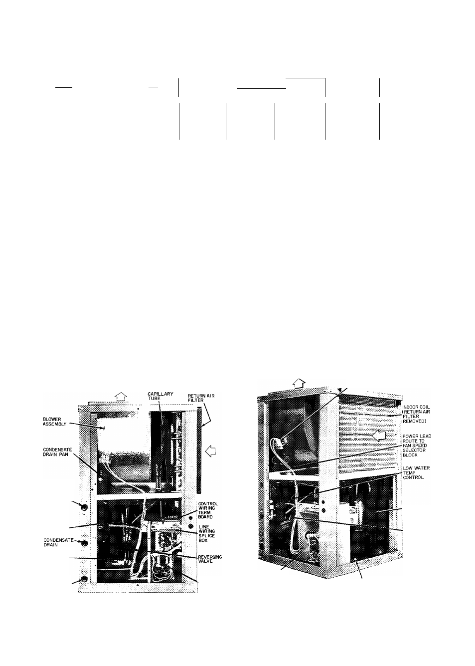
FAN SPEED SELECTION BLOCK
(MOLE.X PLUG)
J FPT WATER
OUTLET CONN
SUCTION
SCHRADER
FITTING
DISCHARGE
SCHRADER
FITTING
J"FPT WATER
INLET CONN
24-V
TRANS
Fig. 5
CONTROL BOX
AIRFLOW
Component Location
6
COMPRESSOR
HEAT
EXCHANGER
COMPRESSOR HOLD-DOWN
BOLTS (4)
i