Carrier 50WQ User Manual
Page 7
Attention! The text in this document has been recognized automatically. To view the original document, you can use the "Original mode".
COOLING CYCLECHARGING CHART
METHOD
L Operate unit a minimum of 10 minutes before
checking charge, and after each charge
adjustment.
2. Measure suction pressure by attaching a gage to
50WQ unit suction service port (Schrader
Fitting).
3. Measure discharge pressure by attaching a gage
to unit discharge service port (Schrader Fitting).
4. Using a sling psychrometer, measure wet-bulb
temperature of air entering unit.
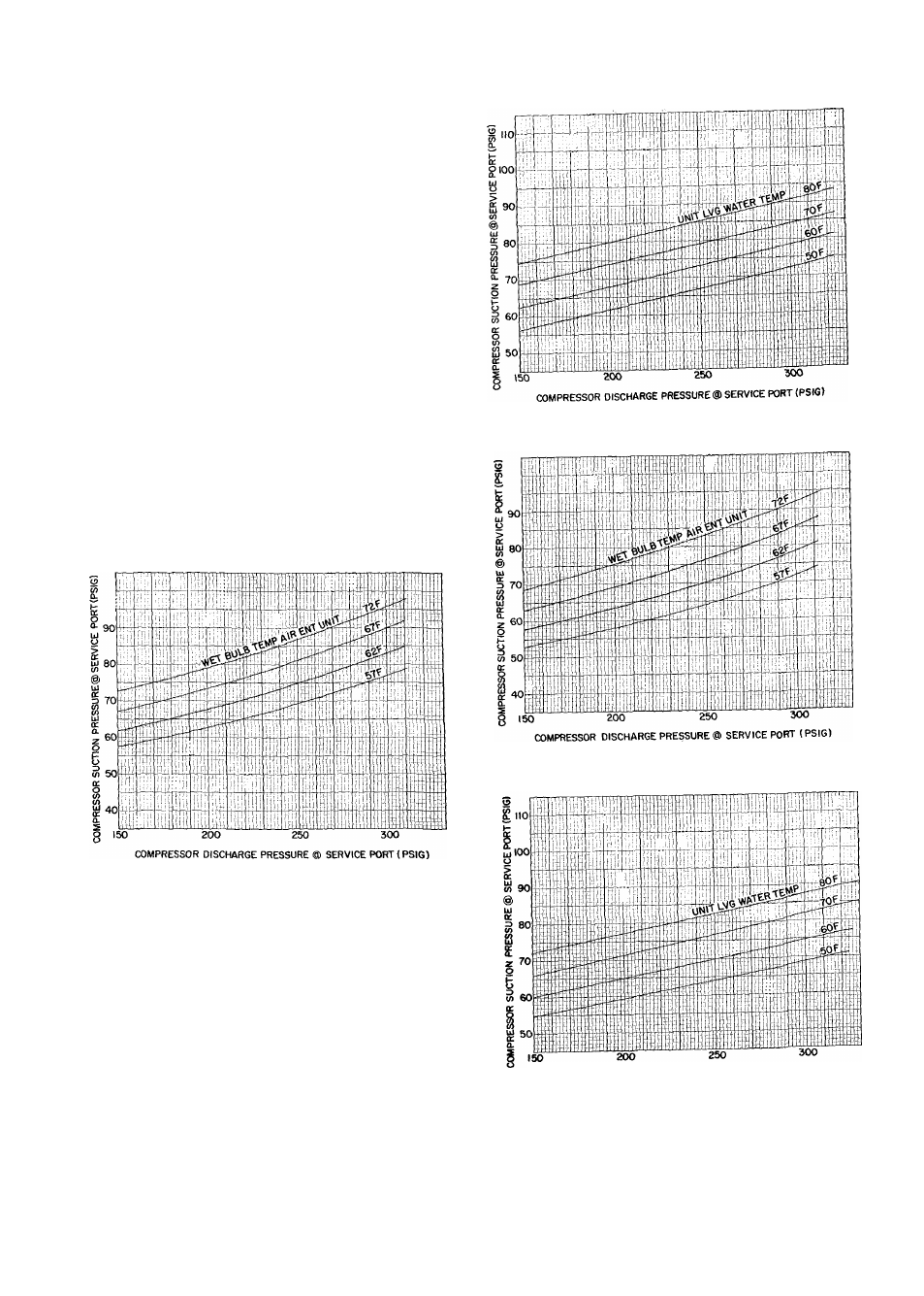
5. Refer to correct Charging Chart. Locate on
curves where unit discharge pressure line and
indoor air wet-bulb temperature line intersect.
6. From intersect point, project horizontally left to
chart suction pressure line. Compare chart
suction pressure to unit suction pressure (step 2).
7. If unit suction pressure is lower than chart pres
sure, add refrigerant to unit until chart pressure
is reached. If unit suction pressure is higher than
chart pressure, remove refrigerant until chart
pressure is reached.
Fig. 6 — 50WQ014 Cooling Cycle
Charging Chart (R-22)
Fig. 7 — 50WQ014 Heating Cycle Operation
Check Chart (R-22)
Fig. 8 — 50WQ018 Cooling Cycle
Charging Chart (R-22)
COMPRESSOR DISCHARGE PRESSURE® SERVICE PORT (PSIG)
Fig. 9 — 50WQ018 Heating Cycle Operation
Check Chart (R-22)