Electrical, A warning, A caution – Carrier 58SS/DH User Manual
Page 5: Start-up, adjustment, and safety check
Attention! The text in this document has been recognized automatically. To view the original document, you can use the "Original mode".
MORE THAN
Fig. 5 — Chimney, Gas Vent Height
Type-BI Gas Vent
— Note that this furnace may
be connected to type-Bl gas vents. Type-Bl vents are
suitable, providing the vent system always operates at
zero or negative pressure. The vent system of this furnace
meets this standard.
For
Replacement
Installations,
Refer
to
Appendix, page 7.
ELECTRICAL
IMPORTANT: Before proceeding with electrical
connections, make certain that voltage, frequency
and phase correspond to that specified on the furnace
rating plate. Also, check to be sure the service pro
vided by the utility is sufficient to handle the addi
tional load imposed by this equipment. Refer to unit
rating plate for equipment electrical requirements.
The specific furnace installation instructions contain
wiring diagrams which show the proper field high- and
low-voltage wiring. Make all connections in accordance
with National Electrical Code and any local codes or
ordinances that apply.
A
WARNING
The cabinet must have an uninterrupted or unbroken
ground according to National Electrical Code,
ANSl/NFPA 70-1984 and local codes to minimize
personal injury if an electrical fault should occur.
Ground may be electrical wire or conduit, approved
for electrical ground when installed in accordance
with electrical codes. Do not use gas piping as
electrical ground.
A
CAUTION
If manual disconnect switch is to be mounted on
furnace, select a mounting location where drill or
fastener will not contact electrical or gas components.
NOTE: Use only copper wire between disconnect switch
and furnace.
Check all electrical connections (both factory and field)
for tightness. This should also be done after the unit has
reached operating temperatures, especially if aluminum
conductors are used.
START-UP, ADJUSTMENT, AND
SAFETY CHECK
Intermittent Ignition Systems
— Check to be sure
all connections have been properly made, then proceed
as follows:
Light furnace, using the procedure outlined on the
lighting instruction plate attached to the furnace.
However, when lighting the pilot for the first time,
perform the following additional steps:
1. If supply line was not purged before connecting fur
nace, it will be full of air. It is recommended that the
ground joint union be loosened, and supply line be
allowed to purge until odor of gas is detected. Never
purge gas lines into a combustion chamber. Imme
diately upon detection of gas odor, retighten the
union. Allow 5 minutes to elapse, then light pilot in
accordance with instructions on furnace.
2. After pilot lights, main burners should light in
25-75 seconds. If main burners do not light within that
time period, adjust pilot flame, allow pilot to cool
for 5 minutes, repeat time check.
3. Locate pilot adjusting screw on top of gas valve.
a. Remove cap screw; turn pilot adjusting screw
counterclockwise to decrease burner-on time delay,
clockwise to increase burner-on time delay.
b. Replace cap screw.
Gas Input
— Determine gas input as follows:
d.
NATURAL GAS
a. Turn off all other gas appliances and pilots.
b. Measure time (in seconds) for gas meter test dial to
complete one revolution.
c. Refer to Table 2 for cu ft of gas per hour.
Multiply cu ft per hour times heating value of gas
(Btu/cu ft). Obtain heating value of gas from local
utility.
Example:
Btuh heating input = Btu/cu ft x cu ft/hr
Heat value of gas = 1070 Btu/cu ft
Time for one revolution of 2 cu ft dial = 72 seconds
Gas rate = 100 cu ft/hr (from Table 2)
Btuh heating input = 1070 x 100 = 107,000 Btuh
Measured gas input should not exceed gas input
shown on unit rating plate.
e.
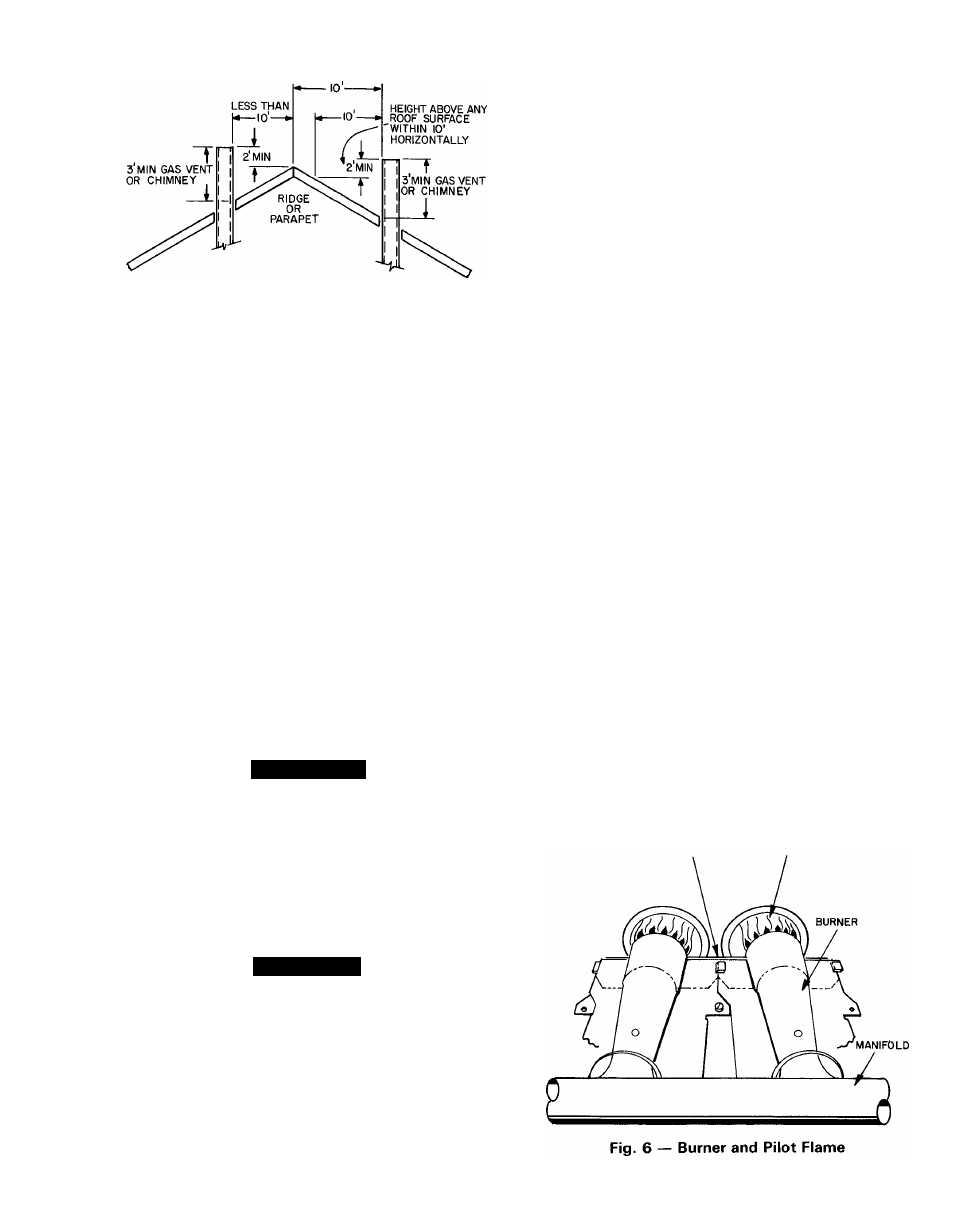
PILOT
flame
BURNER FLAME