Table 5 — chargemaster charging char)t – Carrier 50HQ User Manual
Page 10
Attention! The text in this document has been recognized automatically. To view the original document, you can use the "Original mode".
COMPRESSOR DISCHARGE PRESSURE®SERVICE PORT(PSIG)
Fig. 18 — Heating Cycle Operation
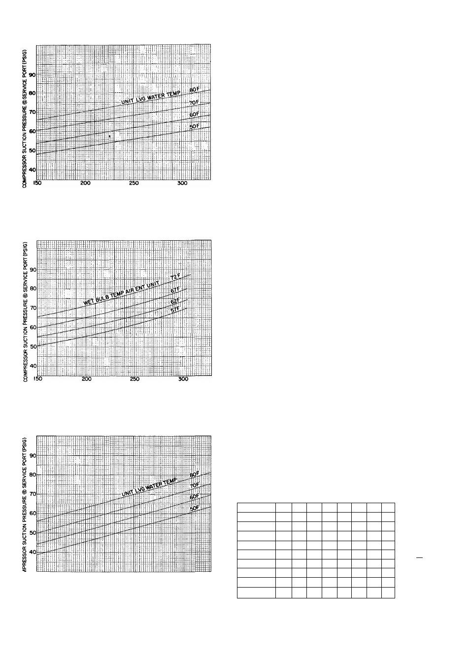
Check Chart (R-22) — 50HQ,VQ033
COMPRESSOR DISCHARGE PRESSURE® SERVICE PORT(PSIG)
Fig. 19 — Cooling Cycle Charging Chart
(R-22) - 50HQ,VQ042
CHARGEMASTER® DEVICE OPERATION
Operate unit 10 minutes before using Charge-
master. Ensure unit indoor fan section access panel
is in place for proper Chargemaster operation.
1. Tape Chargemaster feeler bulb to unit suction
line. Insulate bulb. Ensure suction line is clean
for good contact with bulb.
2. Connect refrigerant drum to Chargemaster inlet
port with drum in position for vapor charging.
3. Connect Chargemaster outlet port (loosely) to
unit suction line Schrader valve.
4. Crack valves on refrigerant drum and Charge-
master to purge lines from drum to suction line
Schrader valve. After purging lines, close valve
on Chargemaster only. Tighten Chargemaster
connection at suction line Schrader valve.
5. Measure unit leaving water temperature.
6.
Read evaporator temperature at red needle
position on Chargemaster temperature gage and
suction
line
temperature
at
black
needle
position.
CAUITON: Do not read evaporator tempera
ture with Chargemaster valve open.
7. Enter 50HQ,VQ Chargemaster Charging Chart,
Table 5, at unit leaving water temperature (step
5) and evaporator temperature (step 6). (Do not
use standard charging chart on cover of Charge-
master.) Find the suction line temperature
required for correct system charge. If actual
suction line temperature (step 6) is higher than
table value, the system is undercharged. If suction
line temperature is lower than table value, the
system is overcharged.
Example: At leaving water temperature of 93 F
and evaporator temperature of 41 F, the system is
correctly charged at 50F ( ± 2 F ) suction line
temperature.
ISO
200
250
300
COMPRESSOR DISCHARGE PRESSURE @ SERVICE PORT(PSIG)
Fig. 20 — Heating Cycle Operation
Check Chart (R-22) — 50HQ,VQ042
Table 5 — Chargemaster Charging Char)t
UNIT
LEAVING
WATER
TEMP
(F)
30 33
36
EVAPORATOR TEMP (F)
44
47
53
56
Suction Line Temp (F)
69
46
49
5Ì
54
57
59
61
75
45
47
50
53
55
58
60
64
81
46
49
51
54
56
57
63
87
48
50
52
54
56
62
93
46
48
50
53
55
57
99
47
49
51
54
56
105
45
47
50
53
56
112
46
49
53
55
117
45
47
52
55
123
46
50
53
65
61
60
59
57
55
64
63
62
61
56”
*Saturated evaporator temperature which is the equivalent tem
perature of pressure taken at unit suction service valve
10