Carrier 38QN User Manual
Page 8
Attention! The text in this document has been recognized automatically. To view the original document, you can use the "Original mode".
To check system operation during heating cycle, use correct
Heating Cycle Check Chart (Fig. 7 through 14). These
charts indicate whether a correct relationship exists
between system operating pressure and air temperatures
entering indoor and outdoor units. If pressure and tempera
ture lines do not intersect on chart, system refrigerant
charge may not be correct or other system abnormalities
may exist. Do not use Heating Cycle Check Charts to adjust
refrigerant charge.
When recharging is necessary during heating season, weigh
in total charge as indicated on unit rating plate. Remove
any refrigerant remedning in system before recharging. If
the system has lost complete charge, evacuate and recharge
by weight. Service port connections are provided on liquid
and suction line service valves. For evacuation and recharg
ing, Dial-A-Charge charging cylinder is an accurate device
for recharging systems by weight.
To check and adjust charge during cooling season, use
Tables 4 and 5 and the following procedure:
1. Operate unit a minimum of 15 minutes before checking
charge.
2. Measure suction pressure by attaching a gage to suc
tion valve service port.
3. Measure suction line temperature by attaching a serv
ice thermometer to unit suction line near suction valve.
Insulate thermometer for accurate readings.
4. Measure outdoor coil inlet air dry-bulb temperature
Table 4—Superheat Charging Table
(Superheat Entering Suction Service Valve)
OUTDOOR
TEMP(F)
55
60
65
70
75
80
85
90
95
100
105
110
115
50 52
12
10
INDOOR COIL ENTERING AIR (F) WB
54
14
12
10
56
17
15
13
10
58
20
18
16
13
60
23
21
19
16
12
62
26
24
21
19
15
12
64
29
27
24
21
18
15
11
66
32
30
27
24
21
18
15
13
10
68
35
33
30
27
24
21
19
16
14
12
70 72 74 76
37
35
33
30
28
25
22
20
18
15
13
11
40
38
36
33
31
28
26
24
22
20
17
15
42
40
38
36
34
31
30
27
25
23
22
20
8 14 18 23
45
43
41
39
37
35
33
31
29
27
26
25
-Do not attempt
refrigerant slugg
to charge system
ing may occur.
under these conditions or
with a second thermometer.
5. Measure indoor coü inlet air wet-bulb temperature with
a sling psychrometer.
6. Refer to Table 4. Find air temperature entering outdoor
coil and wet-bulb temperature entering indoor coil. At
this intersection, note the superheat.
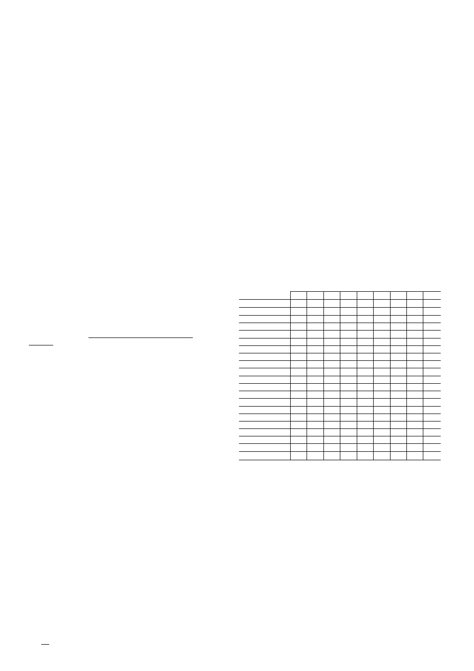
7. Refer to Table 5. Find superheat temperature and suc
tion pressure, and note suction line temperature.
8. If unit has higher suction line temperature than
charted temperature, add refrigerant until charted tem
perature is reached.
9. If unit has lower suction line temperature them charted
temperature, bleed refrigerant until charted tempera
ture is reached.
10. If air temperature entering outdoor coU or pressure at
suction valve changes, charge to new suction line tem
perature indicated on chart.
11. This procedure is valid, independent of indoor air
quantity.
NOTE: For service data, refer to separate service manual
for Models 38EH,EN,ES,QH,QN,QS.
Table 5—Required Suction-Tube Temperature (F)
(Entering Suction Service Vaive)
TEIWP(F)
61.5 64.2 67.1 70.0 73.0 76.0 79.2 82.4 85.7
0
35
37
39
41
43
45
47
49
51
2
37
39
41
43
45
47
49
51
53
4
39
41
43
45
47
49
51
53
55
6
41
43
45
47
49
51
53
55
57
8
43
45
47
49
51
53
55
57
59
10
45
47
49
51
53
55
57
59
61
12
47
49
51
53
55
57
59
61
63
14
49
51
53
55
57
59
61
63
65
16
51
53
55
57
59
61
63
65
67
18
53
55
57
59
61
63
65
67
69
20
55
57
59
61
63
65
67
69
71
22
57
59
61
63
65
67
69
71
73
24
59
61
63
65
67
69
71
73
75
26
61
63
65
67
69
71
73
75
77
28
63
65
67
69
71
73
75
77
79
30
65
67
69
71
73
75
77
79
81
32
67
69
71
73
75
77
79
81
83
34
69
71
73
75
77
79
81
83
85
36
71
73
75
77
79
81
83
85
87
38
73
75
77
79
81
83
85
87
89
40
75
77
79
81
83
85
87
89
91
Manufacturer reserves the right to discontinue, or change at any time, specifications or designs without notice and without incurring obligations.
^ I
^
PC 101 Catalog No. 533-820
Printed in U.S.A.
Form 38QN-10SI
10-87 Pg 8
Tab 15a 15a
Replaces: 38QN-9SI