Fig. 4—line power connections, A caution, Fig- 5—determining amp draw – Carrier 38QN User Manual
Page 4
Attention! The text in this document has been recognized automatically. To view the original document, you can use the "Original mode".
CONNECT GROUND LEAD AND POWER WIRING-
Connect ground lead to ground connection in control box for
safety. Then connect power wiring. See Fig. 4. Splice line
power leads to yellow and black pigtails. Use wire nuts and
tape at each connection. Connect unit wiring to copper
power wiring only.
CONNECT CONTROL POWER WIRING-Route 24-v
control wires through control wiring hole and channel and
connect leads to control wiring terminal board. See Fig. 1
and 6.
Use furnace or fan coil transformer as 24-v (40-va minimum)
supply for system as shown in Fig. 6, or use accessory
transformer.
l-PHASE
CONN. TO
'---GROUND LEAD-
-[H
groundin
'
g
lug
DISCONNECT
PER NEC
---- .---------
— YEL-------------------
I- PHASE
SPLICE CONNECTIONS
COND UNIT
----------------FIELD WIRING
--------------- FACTORY WIRING
3-PHASE
CONN. TO
DISCONNECT
PER NEC
--GROUND LEAD -
-UlGROUNDING LUG
3-PHASE UNIT
--------------Field Wiring
-------------- Factory Wiring
Fig. 4—Line Power Connections
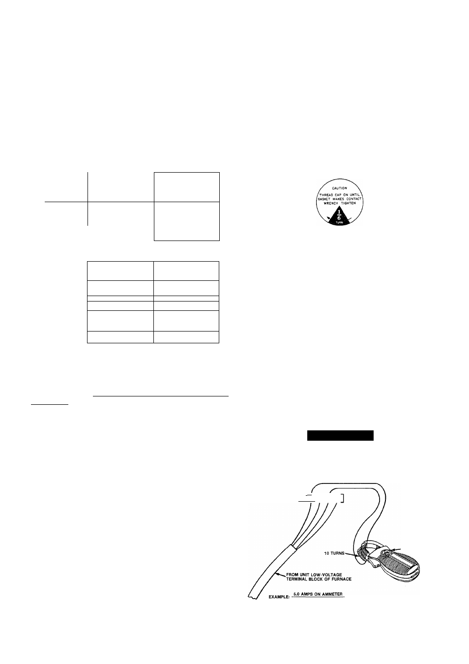
Step 5—Start-Up—
Heat Anticipator Settings for Room
Thermostat. To set the heat anticipator, move the heat
anticipator to the maximum setting. Determine which ter
minal powers the electric heater controls. With the heaters
energized, measure the amperage between the appropriate
W terminal and R and set the anticipator to the same valve.
Fig. 5 illustrates an easy method of obtaining the actual
amp draw.
Accessory Outdoor Thermostat
provides adjustable out
door control of accessory electric heater. This thermostat
makes contact when a drop in outdoor temperature occurs.
It energizes a stage of electric heat when the outdoor tem
perature setting is reached, provided the room thermostat
is on the second stage of heating. One outdoor thermostat is
recommended for each stage of electric heat after the first
stage. Set the outdoor thermostat(s) progressively lower for
each stage. Refer to heat load of building and unit capacity
to determine the correct outdoor thermostat settings.
The accessory supplemental heat relay is required when 2
outdoor thermostats are used. It is automatically energized
by the manually operated supplemental heat switch in the
indoor thermostat subbase. The thermostat locks out com
pressor and the relay bypasses the outdoor thermostats for
electric heater operation during heat pump shutdown. When
one outdoor thermostat is used, a supplemental heat relay is
not required. The supplemental heat switch in the indoor
thermostat subbase bypasses outdoor thermostat, locks out
compressor and activates electric heater.
MOUNT OUTDOOR THERMOSTAT in control box.
Attach brackets with short sheet metal screws to avoid con
tact with coH. Leave capUlary tube coiled in control com
partment making sure it is clear of aU electrical connections
and sharp metal edges.
MOUNT SUPPLEMENTAL HEAT RELAY in convenient
location on indoor unit. Attach with sheet metal screw.
To Start Unit
1. Energize crankcase heater a minimum of 24 hours
before starting unit. To energize heater only, set ther
mostat at OFF position and close electrical disconnect
to outdoor unit.
2. Backseat (open) liquid and suction line service valves.
4.
5.
6
.
7.
8
.
Unit is shipped with valve stem(s) frontseated, and
caps installed. Replace stem caps after system is
opened to refrigerant flow (backseated). Replace caps
finger tight and tighten additional % turn with wrench.
See sticker on valve cap.
Turn on main disconnect switch(es) to indoor and out
door units.
Set fan switch as desired (ON or AUTO).
Set thermostat dial at desired temperature.
Set selector switch at HEAT or COOL. Operate unit
for 15 minutes.
Check system refrigerant charge. See Refrigerant
Charging.
Motors and controls are designed to operate satisfactorily
in the voltage range shown in Table 3. If necessary to use
manifold gages for servicing, refer to Carrier Standard Serv
ice Techniques Manual, Chapter 1, Refrigerants, Pages 1-5,
Fig. 8 for bypass method of returning charge to system.
Removal of liquid line charging hose without following
these precautions could result in some loss of charge.
Refrigerant Charging
(Fig. 7 through 14)
A CAUTION
To prevent personal injury, wear safety glasses and
gloves when handling refrigerant. Do not overcharge
system. This can cause compressor failure.
THERMOSTAT
I
—^
A
TERMINALS"--- ® 0 ® ©
HOOK'AROUNO
VOLT/AMMETER
10 TURNS AROUND JAWS
0.5 AMPS FOR THERMOSTAT SETTING
Fig- 5—Determining Amp Draw