A caution, Fig. 2—accurater (bypass type) components, Table 1—physical data – Carrier 38QN User Manual
Page 2: Table 2—accurater™ chart
Attention! The text in this document has been recognized automatically. To view the original document, you can use the "Original mode".
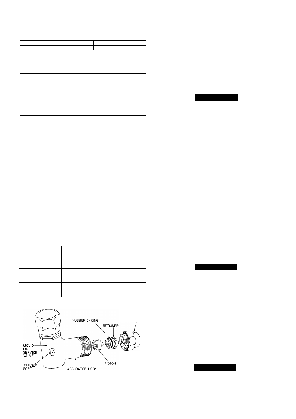
Table 1—Physical Data
MODEL 38QN
015
018
024
030
036
042
048
060
OPER WT (lb)*
132
151
155
180
195
189
235
270
REFRIGERANT
Control
22
AccuRater'^'^ (Bypass Type)
CONDFAN
Air Discharge
AirQty(Cfm)
Mtr Rpm (60 Hz)
Propeller Type, Direct Drive
Vertical
1850 1 2400 1 3100 1 3800 | 4000 | 5000
830 1 1075 850 | 1075 | 840
CONDCOIL(fins/in.)
Tube Diam
Rows
Refrig Ckts
Face Area (sq ft)
1
Vin.
1
2 2
12.77
6
E-Coil
2 1 3 1
17.33
)
21.88
DIMENSIONS (ft-in.)
Diameter A
Height B
1-9%
2-574
2-7
3-2%
CONNECT, (in. ODF)
Suction
Liquid
Compatible Fitting (Suction) & Flare (Liquid)
% 1 %
%
REFRIG LINES
(in. ODF)
Suction
Liquid
%
%
%
1%t
♦Weight increases slightly with addition of any accessories.
t38QN048-060 require lYs-in. suction line for optimum perform
ance. A %- X 17s-in. connection adapter accessory (Carrier Part
No. 28AU900061) is available. If a 7s-in. accessory tubing pack
age is used, expect a slight capacity loss.
When installing, allow sufiBcient space for edrflow clearance,
wiring, refrigerant piping and servicing. Maintain a mini
mum of 4 ft clearance from obstructions above and 18 in.
around unit (12 in. on valve side). Maintedn a distance of 24
in. between heat pumps. Position so water or ice from roof
or eaves cannot fall directly on unit.
Step 2—Replace Indoor AccuRater™ Piston, if Required-
Check indoor cod piston to see if it matches the required pis
ton listed in Table 2. If it does not match, replace indoor cod
piston with piston shipped with this outdoor unit (located in
plastic bag taped to valves). See Fig. 2.
Table 2—AccuRater™ Chart
OUTDOOR
UNIT
38QN
OUTDOOR
PISTON
INDOOR
PISTON
015
35
46
018
40
49
024
46
59
030
55
65
036
61
73
042
67
73
048
73
82
060
78
101
FLARE NUT
Step 3—Make Piping Connections—
Outdoor units may be
connected to indoor sections using Carrier accessory tubing
package or field-supplied tubing of refrigerant grade, cor
rect size and condition (Table 1). For tubing requirements
beyond 50 ft, obtain information from local Carrier
distributor.
Outdoor
Units
Connected
to
Carrier-Approved
Indoor
Units—
Outdoor units contain correct system refrigerant
charge for operation with indoor unit of the same size when
connected by 25 ft of field-supplied or Carrier accessory tub
ing. Check refrigerant charge for maximum efficiency.
A CAUTION
DO NOT BURY MORE THAN 3 FT OF REFRIGER
ANT TUBING IN GROUND. If any section of tubing
is buried, there must be a 6-in. vertical rise to valve con
nections on outdoor unit. If more than the recom
mended length is buried, refrigerant may migrate to
cooler buried section during extended periods of unit
shutdown. This causes refrigerant slugging and possi
ble compressor damage at start-up.
CONNECT REFRIGERANT LINES to fittings on unit
suction and liquid service valves (Fig. 1). Liquid service
valve has flare fitting; suction service valve has Compatible
Fitting. Make suction line connection first. Slide flare nut
on liquid line, then flare and connect liquid line. Use a maxi
mum torque of 15 ft-lb to tighten flare nut. (Do not disas
semble AccuRater.) Unit Compatible Fitting permits
mechanical or sweat connection as described below.
Models 38QN048,060—When using iVs in. field-supplied
refrigerant suction line, sweat-connect suction line to lYs in.
end of required connection adapter. Be sure to provide a
heat sink at the service valve to prevent damage during
sweating operation. Connect %-in. end of adapter to unit suc
tion line Compatible Fitting. Connect liquid refrigerant line
to unit. When a 7s-in. field-supplied suction hne is used, pro
vide a field-supplied %-in. to 7s-in. suction line adapter (not
necessary if 38LS accessory tube is used).
NOTE: Compatible Fitting on outdoor section has alumi
num plug located beneath compatible nut on suction valve.
Plug keeps contaminants out of Compatible Fitting.
A CAUTION
When removing compatible nut, be careful pressure
build-up does not cause aluminum plug to blow and
cause personal injury. After tubing is hooked up, dis
card plug.
A87151
Fig. 2—AccuRater (Bypass Type) Components
Mechanical Connection—Mate one set of connections at a
time.
1. Remove nut on Compatible Fitting.
2. Remove plug and be sure 0-ring is in the groove inside
the Compatible Fitting.
3. Cut tubing to correct length. Deburr and size as neces
sary. Slide nut onto tube.
4. Insert tube into Compatible Fitting until it bottoms.
Tighten nut until it bottoms on shoulder of fitting or
valve. Keep tube bottomed in Compatible Fitting while
tightening nut.
A CAUTION
If undersized, damaged or eUipticaUy-shaped tubing is
used when making Compatible Fitting, leaks may
result.