Carrier 38QN User Manual
Page 3
Attention! The text in this document has been recognized automatically. To view the original document, you can use the "Original mode".
Sweat Connection—Use refrigerant grade tubing.
1. Remove locking nut, plug, rubber 0-ring and Schrader
core and cap from valve service port.
2. Cut tubing to correct length. Deburr and size as
necessary.
3. Insert tube in Compatible Fitting until it bottoms.
NOTE: Wrap top and bottom of service valves in wet
cloth to prevent damage by heat. Solder with low-
temperature (430 F) silver edloy solder.
4. Replace Schrader core and cap.
5. Evacuate or purge system with field-supplied
refrigerant.
Compatible Fitting Repair
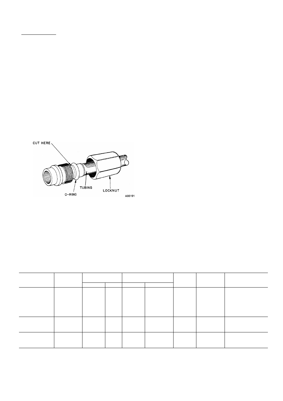
MECHANICAL CONNECTION-Frontseat unit service
valves. Relieve refrigerant pressure from tubing. Back off
locknut from Compatible Fitting onto tube. Cut fitting
between threads and 0-ring. See Fig. 3. Remove tubing sec
tion remaining in threaded portion of fitting. Discard
locknut.
COMPATIBLE FITTING
Clean, flux and insert new tube end into remaining portion
of Compatible Fitting. Wrap valve in wet rag to prevent
damaging factory-made joints. Heat and apply low-tempera
ture (430 F) solder.
SWEAT CONNECTION-Frontseat unit service valves.
Relieve refrigerant pressure from tubing. Clean and flux
around leak. Repair, using low-temperature (430 F) solder.
Evacuate or purge evaporator coil and tubing system. Add
refrigerant charge. See Refrigerant Charging.
Step 4—Make Electrical Connections—
Be sure field wir
ing comphes with local and national fire, safety and electri
cal codes, and voltage to system is within limits shown in
Table 3. Contact local power company for correction of
improper fine voltage.
NOTE: Operation of unit on improper line voltage consti
tutes abuse and could affect Carrier warranty. See Table 3.
Do not install unit in system where voltage may fluctuate
above or below permissible limits.
See Table 3 for recommended fuse sizes. When making elec
trical connections, provide clearance at unit for refrigerant
piping connections.
INSTALL BRANCH CIRCUIT DISCONNECT PER NEC
of adequate size to handle unit starting current. Locate dis
connect within sight from and readily accessible from unit,
per Section 440-14 of National Electrical Code (NEC).
ROUTE LINE POWER LEADS-Extend leads from dis
connect through power wiring hole provided (see Fig. 1) and
into unit splice area. Remove control box cover to gain
access to unit wiring.
Fig. 3—-Repair of Mechanicai Connection
Tabie 3—Eiectricai Data (60 Hz)
Three-phase availabie with 036-060 sizes
OUTDOOR
UNIT 38QN
V/PH
OPER VOLTS*
COMPR
FAN
FLA
MCA
MAX FUSEt OR
HACR TYPE
CKTBKRAMPS
Max
Min
LRA
RLA
015-32
35.0
7.2
0.7
9.7
15
018-33
49.0
10.5
0.7
13.8
20
024-32
53.0
13.2
2.1
18.6
30
030-34
208-230/1
253
197
70.0
17.6
1.9
24.1
40
036-31
86.7
18.9
0.9
24.5
40
042-31
108.0
21.8
2.6
29.9
50
048-31
110.0
27.3
1.9
36.0
60
060-31
142.0
33.0
2.1
43.4
60
036-51
65.0
11.5
0.9
15.3
25
042-51
208/230/3
254
187
80.0
13.3
2.5
19.1
30
048-51
92.0
14.7
1.9
20.2
30
060-51
130.0
21.4
2.1
28.9
, 45
036-61
32.8
5.1
1.6
8.0
15
042-61
460/3
506
414
35.0
7.2
1.6
10.6
15
048-61
46.0
7.0
1.6
10.4
15
060-61
65.0
9.6
1.6
13.9
20
FLA
—Full Load Amps
HACR—
Heating, Air Conditioning, Refrigeration
LRA
—Locked Rotor Amps
MCA
—Minimum Circuit Amps
RLA
—Rated Load Amps
NOTE: Control circuit is 24 v on all units and requires external power source.
♦Permissible limits of the voltage range at which unit will operate
satisfactorily.
tTime-delay fuse.