2 — 48kha.kla suggested rigging, Step 1, Installation rig and place unit – Carrier 48KHA User Manual
Page 2: Table 1 — perferjpiance data
Attention! The text in this document has been recognized automatically. To view the original document, you can use the "Original mode".
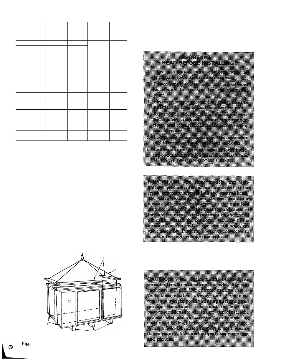
Table 1 — Perferjpiance Data
MODEL 48-
COOLING
CAPACITY
(Btuh)*
RATED
HEATING
INPUT
(Btuh)
OUTPUT
CAPACITY
(Btuh)
ARIt
SOUND
RATING
(Bels)
KLA118310BE
17,800
40,000
32,000
7.8
KLA124310BE
23,800
40,000
32,000
7 8
KHA024310BF
24,000
75,000
58,000
8.0
KLA130310BE
29,600
40,000
32,000
7 8
KHA030310BF
29,600
75,000
58,000
7.8
KLA136310BE
36,000
60,000
47,000
8 0
KLA036510CE
36,000
60,000
45,000
80
KLA036610CE
36,000
60,000
45,000
8 0
KHA136310BE
36,000
100,000
79,000
80
КНА036510СЕ
36,000
100,000
75,000
80
KHA036310BF
36,000
125,000
97,000
80
KHA036510CF
36,000
1 25,000
93,750
8.0
KLA142310BE
42,000
60,000
47,000
78
KLA042510CE
42,000
60,000
45,000
7 8
KHA042310BF
42,000
125,000
97,000
7 8
KHA042510CF
42,000
125,000
93,750
7.8
KLA148310BE
49,000
80,000
63,000
8 4t
KLA048510CE
49,000
80,000
60,000
8 41
KLA048610CE
49,000
80,000
60,000
8 41
KHA048310BF
49,000
125,000
97,000
8 41
KHA048510CF
49,000
125,000
93,750
8.41
KLA160310BE
60,000
100,0001:
79,000$
8 41
KHA060310BF
60,000
1 50,0001
11 6,0001
8 41
*Rated in accordance with U S Government DOE test procedures and/or
ARI Standard 210-81
tSound rating per ARI 270-84
^The capacity ratings of single-phase units are in accordance with U S
Government DOE test procedures and/or AGA certification require
ments For 3-phase units, the efficiency rating is a product thermal
efficiency
rating
determined
under
continuous
operating
conditions,
independent of any installed system
Units with number 1 in the 4th digit location of
model number in Table 1 meet California oxides of
nitrogen (NOx) maximum emission requirements.
Units are factory charged with R-22 refrigerant.
To install; connect gas supply, air ducts, high- and
low-voltage wiring and condensate drain, and install
a field-supplied air filter in the return-air ductwork.
All units can be connected into existing duct
systems that are properly sized and designed to
handle an airflow of350 to 450 cfm per each 12,000
Btuh of rated coaling capacity. See Table 8 for cool
ing and heating airflow requirements.
NOTE: When installing any accessory item, see
Installation Instructions packaged with accessory.
SPREADER BARS:
(2)2x4"xUNIT LENGTH PLUS lO" WITH
DEEP 90° NOTCHES EA(iH END
(2) ¿iiAxUNIT WIDTH WITH 1^
DEEP 90° NOTCHES
EACH END
SPREADER BARS
LOCATE CHAINS THROUGH
HOLES IN BASE
CHANNELS
CHAIN
TWO OR THREE BASE
CHANNELS ATTACHED TO
BOTTOM OF UNIT
2 — 48KHA.KLA Suggested Rigging
Step 1
INSTALLATION
Rig and Place Unit