Carrier 48KHA User Manual
Page 13
Attention! The text in this document has been recognized automatically. To view the original document, you can use the "Original mode".
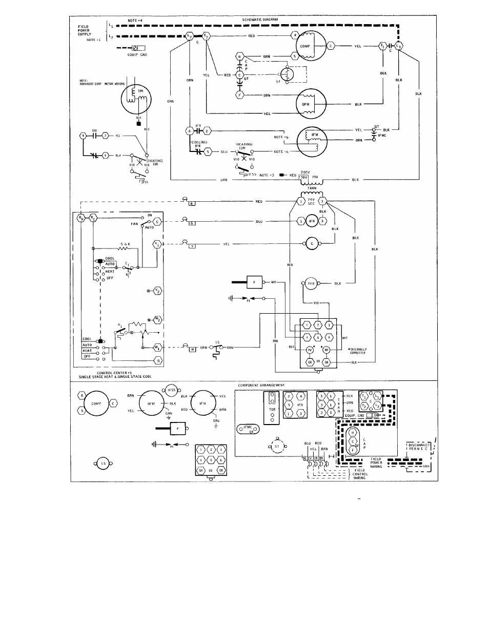
C — Contactor
Cap. — Capacitor
Comp — Compressor
GV — Gas Valve
IFM
— Indoor Fan Motor
IFMC
— Indoor Fan Motor Capacitor
IFR “ Indoor Fan Relay (Cooling)
IFSS — Indoor Fan Safety Switch
LS
— Limit Switch
OFM
— Outdoor Fan Motor
P
— Pilot (Safety, Flame Sensing)
PI
— Pilot Igniter
QT
— Quadruple Terminal
ST
— Start Thermistor
TDR — Time-Delay Relay (Adjustable) (Heating)
Tran — Transformer
Wire Sleeve
Component Connection (Unmarked)
o
Component Connection (Marked)
______ Field Wiring
——- Field Ground Wiring
■ WHHS Field Power Wiring
Field Splice
Junction
^ I - Junction (Thermostat to Subbase)
Alternate Start Thermistor Wiring
NOTES:
1 Use copper conductors only
2 Compressor and fan motors thermally protected
3
Transformer pigtails: red 208 v; orange 230 v;
insulate unused lead
4 Neutral for 240/416-v system for Canada only
5
If any of the original wire furnished must be
replaced, it should be replaced with wire of the
same type or its equivalent
6
Fan motor pigtails; red low, black high, insulate
unused lead
Fig. 10 — Typical Wiring Diagram (48KHA030310 shown)
13