Indoor airflow and adjustments – Carrier 48KHA User Manual
Page 17
Attention! The text in this document has been recognized automatically. To view the original document, you can use the "Original mode".
INDOOR AIRFLOW AND ADJUSTMENTS
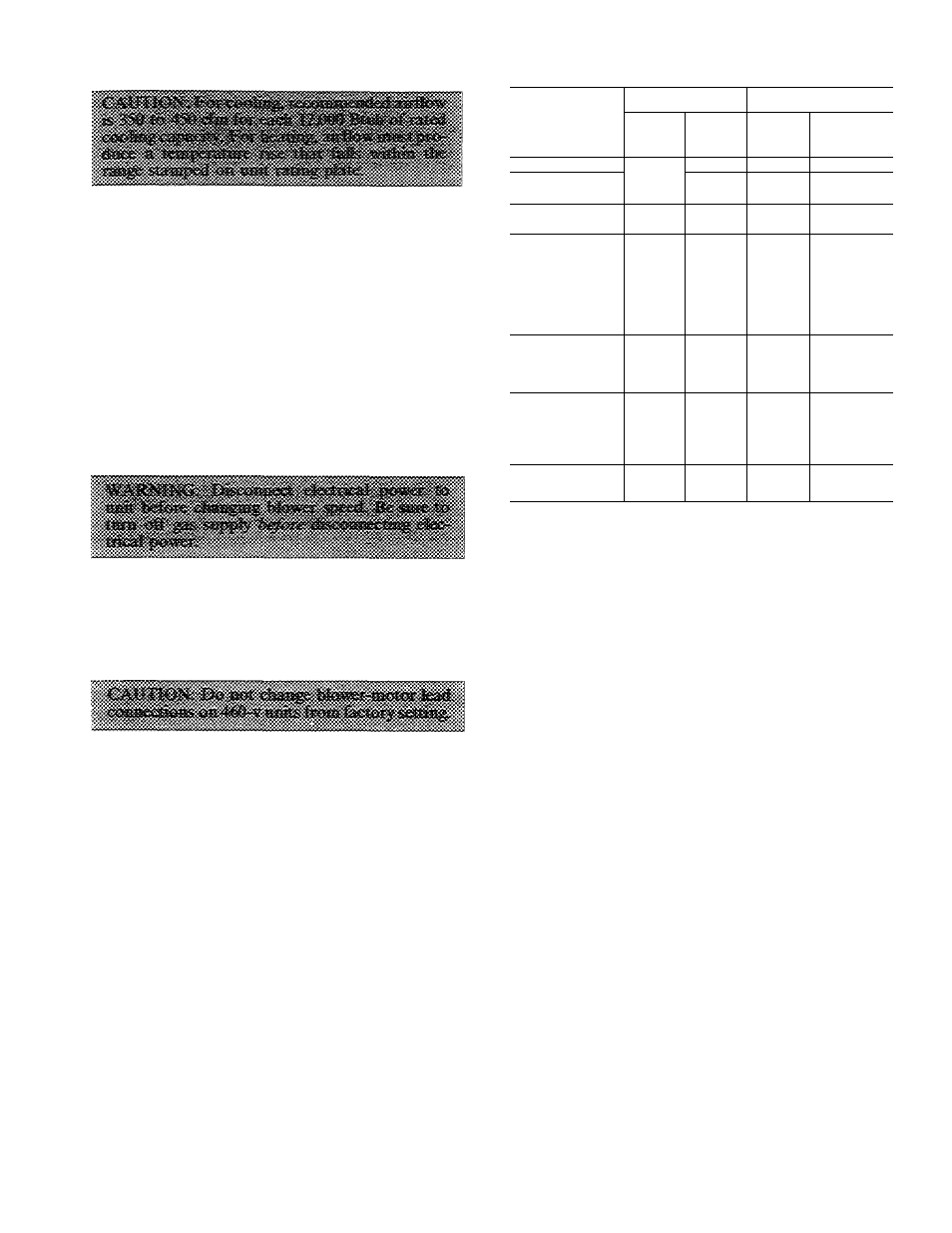
Table 8 — Rated Cooling and Heating Airflows
Models 48KHA,KLA end-discharge units have
direct-drive blower motors. All motors are factory-
connected to deliver proper heating and cooling
airflows at normal external static pressures (except
for some 208-v applications).
Table 5 shows heating airflow at various tempera
ture rises. Table 6 shows both heating and cooling
airflows at various external static pressures for
Models 48KHA,KLA direct-drive units. Refer to
these tables to determine airflow for system being
installed. See Table 8 for rated cooling and heating
airflows.
NOTE; Be sure all supply- and return-air grilles are
open, free from obstructions and adjusted properly.
MODEL 48-
COOLING
HEATING
Rated
Airflow
(cfm)*
ESP
(in.wg)
Rated
Airflow
(cfm)*
Maximum
ESP
(in.wg)*
KLA118310BE
630
0 10
505
0.30
KLA124310BE
800
0 10
505
0 30
KHA024310BF
800
0 10
947
0 30
KLA130310BE
1000
0 15
462
0 30
KHA030310BF
1000
0 15
947
0.30
KLA136310BE
1200
0 15
758
0 30
KLA036510CE
1200
0 15
758
0 65
KLA036610CE
1200
0 15
758
0.65
KHA136310BC
1200
0 15
1155
0 30
KHA036510CE
1200
0 15
1155
0 65
KHA036310BF
1200
0 15
1445
0 30
KHA036510CF
1200
0 15
1445
0 65
KLA142310BE
1400
0 15
695
0 30
KLA042510CE
1400
0 15
695
0 65
KHA042310BF
1400
0 15
1445
0 30
KHA042510CF
1400
0 15
1445
0 65
KLA148310BE
1600
0 20
925
0 30
KLA048510CE
1600
0 20
925
0 65
KLA048610CE
1600
0 20
925
0 65
KHA048310BF
1600
0 20
1445
0 30
KHA048510CF
1600
0 20
1445
0.65
KLA160310BE
2000
0 20
1155
0 30
KHA060310BF
2000
0 20
1735
0 30
ESP — External Static Pressure
*Rated in accordance with U S Government D.O.E test pro
cedures and/or ARl Standard 210-81
NOTE: When operating the 208/230-volt, 3-phase
versions of Models 48KHA048 and 48KHA060 at
208 volts, lead connections of blower motor must
be changed as indicated on unit wiring label to
ensure proper airflow.
Heating and/or cooling airflow of 208/230-v
direct-drive blower motors can be changed by
changing the lead connections of blower motor.
Motor leads are color-coded as follows:
black — high speed
blue — medium speed
red — low speed
NOTE: Some direct-drive blower motors do not
have lead for medium speed. Factory connections
and available optional connections are shown in
Table 6.
For all units, motor lead connected to heat relay
determines heating speed and resulting airflow; and
motor lead connected to cooling relay determines
the cooling speed and resulting airflow. See unit
wiring label.
To change heating and/or cooling speed, connect
appropriate color-coded lead to appropriate relay.
Be sure to properly insulate any unused motor lead.
See Make Wiring Connections, Special Procedures
for 208-v Operation section for proper procedures to
insulate an unused electrical lead.
When installing a 208- or 230-v direct-drive unit
that is factory-connected for heating and cooling
speeds that are not the same, and same speed for
both heating and cooling is required for a particular
application, connect appropriate color-coded lead
to terminal 2 of cooling relay and connect a field-
supplied jumper between heat relay and terminal 2
of cooling relay. Be sure to properly insulate unused
motor lead(s).
17