Carrier 48KHA User Manual
Page 6
Attention! The text in this document has been recognized automatically. To view the original document, you can use the "Original mode".
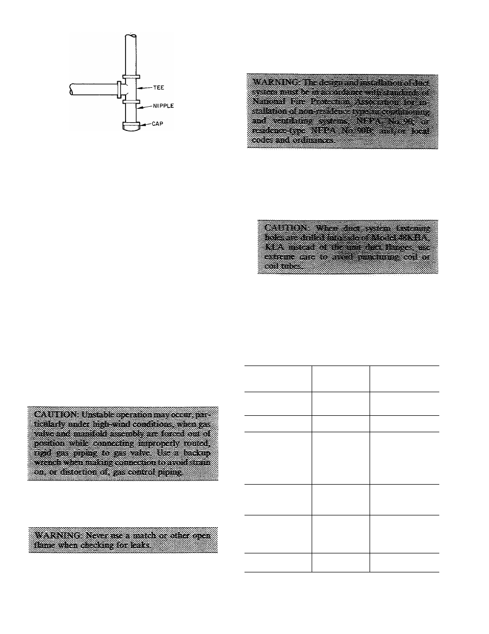
Fig. 7 — Sediment Trap
5. Install an accessible, external, manual shutoff
valve in gas supply pipe within 6 ft of heating
section.
NOTE: The unit manual shutoff valve has a
1/8-in. tapping on the inlet side of this shutoff
for measuring gas input pressure.
6. Install ground-joint union close to heating sec
tion between unit manual shutoff and external
manual main shutoff valve.
7. Pressure-test all gas piping in accordance with
local and national plumbing and gas codes before
eonnecting piping to unit.
NOTE: When pressure-testing the gas supply
system after the gas supply piping has been con
nected to the unit gas valve, the supply piping
must be disconnected from the gas valve during
any pressure testing of the piping systems at test
pressure in excess of 0.5 in. psig. When pressure
testing the gas supply piping system at test pres
sures equal to or less than 0.5 in. psig, the unit
heating section must be isolated from the gas
piping system by closing the external main
manual shutoff valve and slightly opening
ground-joint union.
8. Where permitted by local codes, use an approved
corrugated metal tubing gas connector between
rigid gas piping and unit manual shutoff.
L
9. Check for gas leaks at all field-installed and
factory-installed gas lines after all piping connec
tions have been completed. Use soap-and-water
solution (or method specified by local codes and/
or regulations).
Step 3 — Make Duct Connections
— Model
48KHA,KLA has duct flanges on the supply-and
return-air openings on side of unit. See Fig. 4 for
connection sizes and locations.
Adhere to the following requirements when se
lecting, sizing and installing duct system:
1. Select and size ductwork, supply-air registers and
return-air grilles according to ASHRAE recom
mendations and as presented in Carrier System
Design Manual, Part 2.
2. Use a flexible transition between rigid ductwork
and unit to prevent transmission of vibration.
The transition may be screwed or bolted to duct
flanges. Use suitable gaskets to ensure a weather-
tight and airtight seal.
Table 2 — Filter Sizes (Field Supplied),
(Sq In.)*
MODEL 48-
STANDARD
DISPOSABLE
TYPE
CLEANABLE OR
HIGH CAPACITY
TYPE
KLA118310BE
302
202
KHA024310BF
454
303
KLA124310BE
384
257
KHA030310BF
480
320
KLA130310BE
480
320
KHA036310BF
694
462
KHA036510CE
576
384
KHA036510CF
694
462 .
KHA136310BE
576
384 >
KLA036510CE
576
384
KLA036610CE
576
384
KLA136310BE
576
384
KHA042310BF
694
462
KHA042510CF
694
462
KLA042510CE
672
448
KLA142310BE
672
448
KHA048310BF
768
512
KHA048510CF
768
512
KLA048510CE
768
512
KLA048610CE
768
512
KLA148310BE
768
512
KHA060310BF
960
640
KLA160310BE
960
640
*Required air filter areas shown are based on the ARI-rated cooling
airflow or the heating airflow at a velocity of 300 fpm depending
on whichever value is larger Air filter pressure drop should not
exceed 0 08 in wg