Table 7 — refrigerant charging label – Carrier 48KHA User Manual
Page 16
Attention! The text in this document has been recognized automatically. To view the original document, you can use the "Original mode".
CHECKING AND ADJUSTING REFRIGER
ANT CHARGE — Refrigerant system is fully
charged with R-22 refrigerant, tested and factory
sealed. For most applications, factory charge is the
correct amount for best performance; however, this
charge may require a slight adjustment to attain
rated performance.
NOTE: Adjustment of refrigerant charge is not re
quired unless unit is suspected of not having proper
R-22 charge. For all applications, correct R-22
charge for best performance is charge that results in
a suction gas superheat of 5 F at compressor inlet
when unit is operating at ARI rating conditions of
95 F db outdoor and 80 F db/67 F wb indoor.
A superheat charging label is attached to outside
of compressor access door. Label includes a Field
Superheat Charging Table and a Required Suction-
Tube (F) temperature chart.
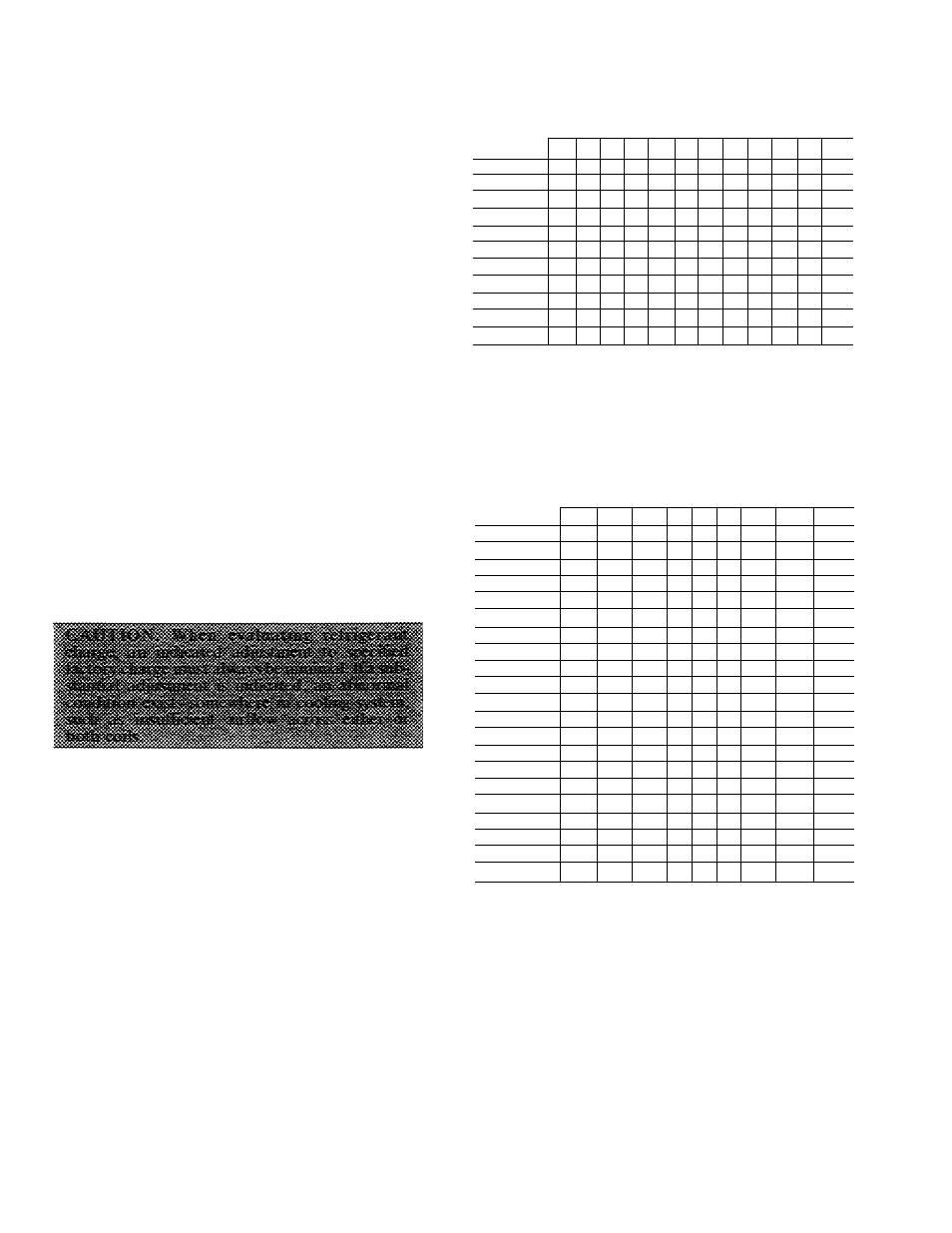
Table 7 is intended for use when minor unit charge
adjustments are required. For large adjustments,
evacuate unit and weigh in charge according to unit
rating plate. Use Table 7 to approximate charge if
ARI rating conditions cannot be obtained. Refer to
required airflow rates in Table 8. Charge unit with
outdoor fan operating only at high speed.
An
accurate
superheat-,
thermocouple-,
or
thermistor-type thermometer, a sling psychrometer
and a gage manifold are required when using super
heat charging method for evaluating unit charge.
Do not use mercury or small dial-type thermometers
because they are not adequate for this type of
measurement.
Proceed as follows:
1. Remove caps from low- and high-pressure serv
ice fittings. See Fig. 4 for location of entrance
for refrigerant pressure gage hoses.
2. Using hoses with valve core depressors, attach
low- and high-pressure gage hoses to low- and
high-pressure service fittings, respeetively.
3. Start unit in cooling mode and let unit run until
system pressures stabilize.
4. Measure and record the following:
a. Outdoor ambient-air temperature (F db).
b. Evaporator inlet-air temperature (F wb).
c.
Suction-tube temperature (F) at low-side
service fitting.
d. Suction (low-side) pressure (psig).
Using Field Superheat Charging Table, compare
outdoor-air temperature (F db) with evaporator
inlet-air temperature (F wb) to determine desired
system operating superheat temperature.
Using Required Suction-Tube (F) table, com
pare desired superheat temperature with suction
Oow-side) operating pressure (psig) to determine
proper suction tube temperature.
5.
6
.
Table 7 — Refrigerant Charging Label
DESIRED SUPERHEAT TEMPERATURE (F)
(Measured @ Low-Side Service Port)
OUTDOOR
EVAPORATOR AIR INLET EWB (F)
EDB (F)
54
56
58
60
62
64
66
68
70
72
74
76
65
10
13
16
19
21
24
27
30
33
36
38
41
70
7
10
13
16
19
21
24
27
30
33
36
39
75
—
6
9
12
15
18
21
24
28
31
34
37
80
—
—
5
8
12
15
18
21
25
28
31
35
85
—
—
__
8
11
15
19
22
26
30
33
90
—
—
—
5
9
13
16
20
24
27
31
95
6
10
14
18
22
25
29
100
—
—
—
—
__
8
12
15
20
23
27
105
5
9
13
17
22
26
110
—
—
—
6
11
15
,
20
25
115
-
-
-
—
-
—
—
8
14
18
23
NOTES:
1 DashedAreas: Do not attempttocharge system undertheseconditionsor
refrigerant slugging may occur
2 Add charge if actual superheat temperature is higher than chart value
and remove if lower Allow ±3F for tolerance
REQUIRED SUCTION-TUBE TEMPERATURE (F) vs.
DESIRED SUPERHEAT TEMPERATURE (F)
(Measured @ Low-Side Service Port)
DESIRED
SUPERHEAT
SUCTION OR LOW-SIDE PRESSURE (Psig)
AT SERVICE PORT
TEMP (F)
61.5
64.2
67.1
70
73
76
79.2
82.4
85.7
0
35
37
39
41
43
45
47
49
51
2
37
39
41
43
45
47
49
51
53
4
39
41
43
45
47
49
51
53
55
6
41
43
45
47
49
51
53
55
57
8
43
45
47
49
51
53
55
57
59
10
45
47
49
51
53
55
57
59
61
12
47
49
51
53
55
57
59
61
63
14
49
51
53
55
57
59
61
63
65
16
51
53
55
57
59
61
63
65
67
18
53
55
57
59
61
63
65
67
69
20
55
57
59
61
63
65
67
69
71
22
57
59
61
63
65
67
69
71
73
24
59
61
63
65
67
69
71
73
75
26
61
63
65
67
69
71
73
75
77
28
63
65
67
69
71
73
75
77
79
30
65
67
69
71
73
75
77
79
81
32
67
69
71
73
75
77
79
81
83
34
69
71
73
75
77
79
81
83
85
36
71
73
75
77
79
81
83
85
87
38
73
75
77
79
81
83
85
87
89
40
75
77
79
81
83
85
87
89
91
NOTE: Measure suction-tube temperature with an accurate superheat
thermocouple, or thermistor-type thermometer
7. Compare actual suction-tube temperature with
proper suction tube temperature. Using a toler
ance of ±3 F, add refrigerant if actual tempera
ture is more than 3 F higher than proper suction
tube temperature, or remove refrigerant if actual
temperature is more than 3 F lower than required
suction-tube temperature.
NOTE: If the problem causing inaccurate readings is
a refrigerant leak, see Unit Preparation, Refrig
erant Leaks section of these instructions.
16