Carrier 48KHA User Manual
Page 7
Attention! The text in this document has been recognized automatically. To view the original document, you can use the "Original mode".
3. Install external, field-supplied air filter(s) in
return-air ductwork where it is easily accessible
for service. Recommended filter sizes are shown
in Table 2.
4. Size all ductwork for maximum required airflow
(either heating or cooling) for unit beinginstalled.
Avoid abrupt duct size increases or decreases.
5. Adequately insulate and weatherproof all duct
work located outdoors. Insulate ducts passing
through an unconditioned space, and use a vapor
barrier in accordance with the latest issue of
SMACNA and NESCA minimum installation
standards for heating and air conditioning
systems. Secure all ducts to building structure.
6. Flash, weatherproof and vibration-isolate all
openings in building structure in accordance with
local codes and good building practices.
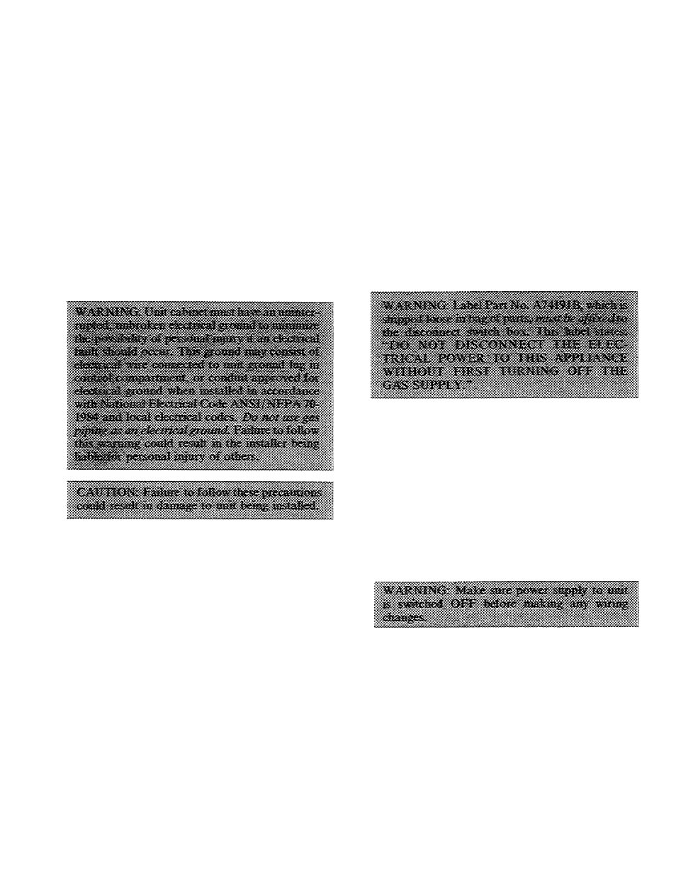
Step 4 — Make Wiring Connections
1. Make all electrical connections in accordance
with National Electrical Code ANSI/NFPA 70-
1984 and local electrical codes governing such
wiring.
2. Use only copper conductor for connections
between the field-supplied electrical disconnect
switch and the unit. Do not use aluminum or
copper-clad aluminum wire.
3. Ensure that high-voltage power to unit is within
operating voltage range indicated on unit rating
plate. On 3-phase units, ensure that phases are
balanced within 2%. Consult local power
company for correction of improper voltage
and/or phase balance.
4. When low-voltage control wires are run in same
conduit as high-voltage wires, insulate low-
voltage wires for highest voltage contained within
conduit.
5. Do not damage internal components when drill
ing through any panel to mount electrical
hardware, conduit, etc.
HIGH-VOLTAGE CONNECTIONS — Unit must
have a separate electrical service with a field-
supplied, waterproof, fused disconnect switch per
NEC mounted near, and within sight from, the unit.
Refer to unit rating plate for maximum fuse size and
minimum circuit amps (ampacity) for wire sizing.
Table 3 shows recommended wire sizes and lengths
based on rating plate data.
The field-supplied disconnect switch box may be
mounted on unit over the high-voltage inlet hole in
control corner panel. See Fig. 4.
Proceed as follows to complete the high-voltage
connections to unit:
1. Connect ground lead to chassis ground connec
tion when using a separate ground wire.
2. Run high-voltage leads into unit control box and
connect to contactor. See unit wiring label and
Fig. 6 and 8.
NOTE: On 3-phase units, connect third high-voltage
lead to brown high-voltage pigtail lead. See unit
wiring label and Fig. 8.
SPECIAL PROCEDURES FOR 208-V
OPERATION
For operation on 208 volts, disconnect orange
transformer-primary lead from contactor. See unit
wiring label and Fig. 6. Remove tape and cover from
terminal on end of red transformer-primary lead.
Save cover. Connect red lead to contactor terminal
from which orange lead was disconnected.
#