Start-up, Unit controls and safety devices, Mût do not jumper low temperar – Carrier 50HQ User Manual
Page 6: Giycoi
Attention! The text in this document has been recognized automatically. To view the original document, you can use the "Original mode".
2. Splice yellow and black power leads from eontrol
box to yellow and red motor leads. (Yellow-to-
yellow and black-to-red.)
CONNECT CONTROL POWER WIRING (24-v)
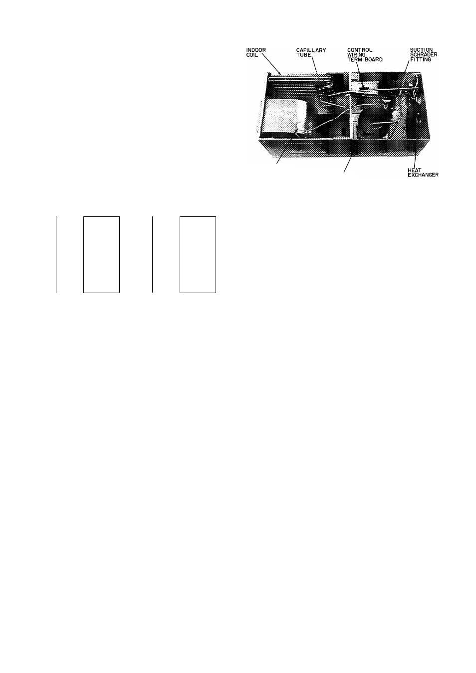
— Power leads are brought thru 1/2-in. hole pro
vided in unit, Fig. 1 and 2. Extend leads to control
wiring terminal board located on top of control box,
Fig. 7. Connect leads to terminal board as shown
in Fig. 6.
Use Carrier-specified room thermostat and sub
base for proper unit operation. Be sure that field-
installed jumper wire is connected between subbase
terminals W and Y. Set thermostat heat anticipator
at 1.0 amp for 1-phase units and 0.50 amp for
3-phase units.
FAN SPEED
SELECTOR BLOCK
(MOLEX PLUG)
COMPRESSOR
Fig. 7 — Typical Component Arrangement
(50HQ014-042 Shown)
1-PHASE
CONN. TO
DISCON NECT-
PER NEC
GROUND
LEAD
—^YEL —
—^BLK —
,__.GROUND
—TSlLUG
3-PHASE
CONN. TO
DISCONNECT-
PER NEC
—
—^YEL —
-TU
yel
—
_iT^YEL
—
50HQ.VQ
HEAT PUMP
CONTROL BOX
GROUND
LEAD
GROUND
—
œilug
50HQ.VQ
HEAT PUMP
CONTROL BOX
I-PHASE
Fig. 6 — Line Power Connections
START-UP
Water Flow and Temperature Data
1. Consider design water flow rates for efficient
operation. See Table 4 for permissible water flow
range.
2. Ensure that water temperature entering unit is
between 60 F minimum and 90 F maximum. If
water temperature below 60 F must be used,
insulate supply line and install a secondary drain
pan under the unit to remove condensate from
heat exchanger and internal plumbing.
CAUTION:
Water
temperature
outside
specified
temperature
rartge
may
cause
damage to
mût Do not jumper low temperar
ture switch in order to use ethytene
giycoi.
3. Ensure that supply water is clean and air is
purged from system. Air in supply water causes
scaling in heat exchanger. Foreign material in
water and/or excessive velocity of water can
cause damage to tubing.
To Start Unit
— Ensure that air filter is in place on
unit filter flanges provided. Do not operate unit
without filter in place. Adjust the thermostat as
follows;
1. Set selector switch at OFF.
2. Turn on main disconnect switch to unit.
3. Set fan switch as desired (ON or AUTO.).
4. Set thermostat dial at desired temperature.
5. Set selector switch at HEAT or COOL.
Check system refrigerant charge. See Service,
Refrigerant Charging on page 7.
Unit
Single-Phase
Compressors
Equipped
With a Compressor Start Thermistor (PTC De
vice)
— When supply voltage is within limits indi
cated on nameplate and compressor will not start,
check the thermistor with an ohmmeter.
If the PTC is good, and the compressor does not
start, disconnect the PTC from the starting circuit
and give unit a temporary capacitanee boost. Refer
to Carrier Standard Service Techniques Manual,
Chapter 2, for details on capacitance boost pro
cedure. If unit does not start with capacitance boost,
compressor may be defective. If unit does start,
check starting capability with PTC assistance. If
questionable, remove PTC, add start capacitor and
start relay per start kit installation instructions.
WARNING: Capadtance boost or iastallatioa
of start capacitor and start relay should be per
formed by trained personnel. Improper pro-
cedure could cause personal injurj' or equipment
damage.
Unit Controls and Safety Devices
HIGH-PRESSURE
RELIEF
VALVE
(except
50HQ,VQ0I4) is located in compressor. Relief valve
opens at a pressure differential of approximately
550 psi between suction (low side) and discharge
(high side) to allow pressure equalization.
CURRENT AND TEMPERATURE SENSITIVE
OVERLOAD (linebreak) — Internal on all com
pressors except on 50HQ,VQ014 which has external
shell mounted overload. Overload resets auto
matically when internal compressor motor tempera
ture drops to a safe level (overloads may require up
to 45 minutes to reset). When an internal overload is
suspected of being open, eheck by using an ohm-