Step 3 — make piping connections – Carrier 50HQ User Manual
Page 3
Attention! The text in this document has been recognized automatically. To view the original document, you can use the "Original mode".
I
MODEL 50HQ
OPERwfob)
"
dimensions
(ft-in.)
A
B
C
D
_E
"
supply
duct
conn
.
(ft-in.)
F
_
_ G
ACCESSORY FILTER (1)
Size (in.)
Table
2
'—
Installation Data — 50HQ (See Fig. 2.)
014
220
018
022
027
033
042
048
195
210
220
230
250
300
3-10-1/2
1-10-5/16
1- 5-15/16
0- 3-7/8
11/16
1-
1-3/8
0- 9^-7/16
17 x23
0- 3-7/8
060
325
080
360
4- 0
1-11
2
-
0
0-2-9/16
0-3-3/16
0-3-1/16
1-7-7/8
1-0
Replaceable Media
37 X 23
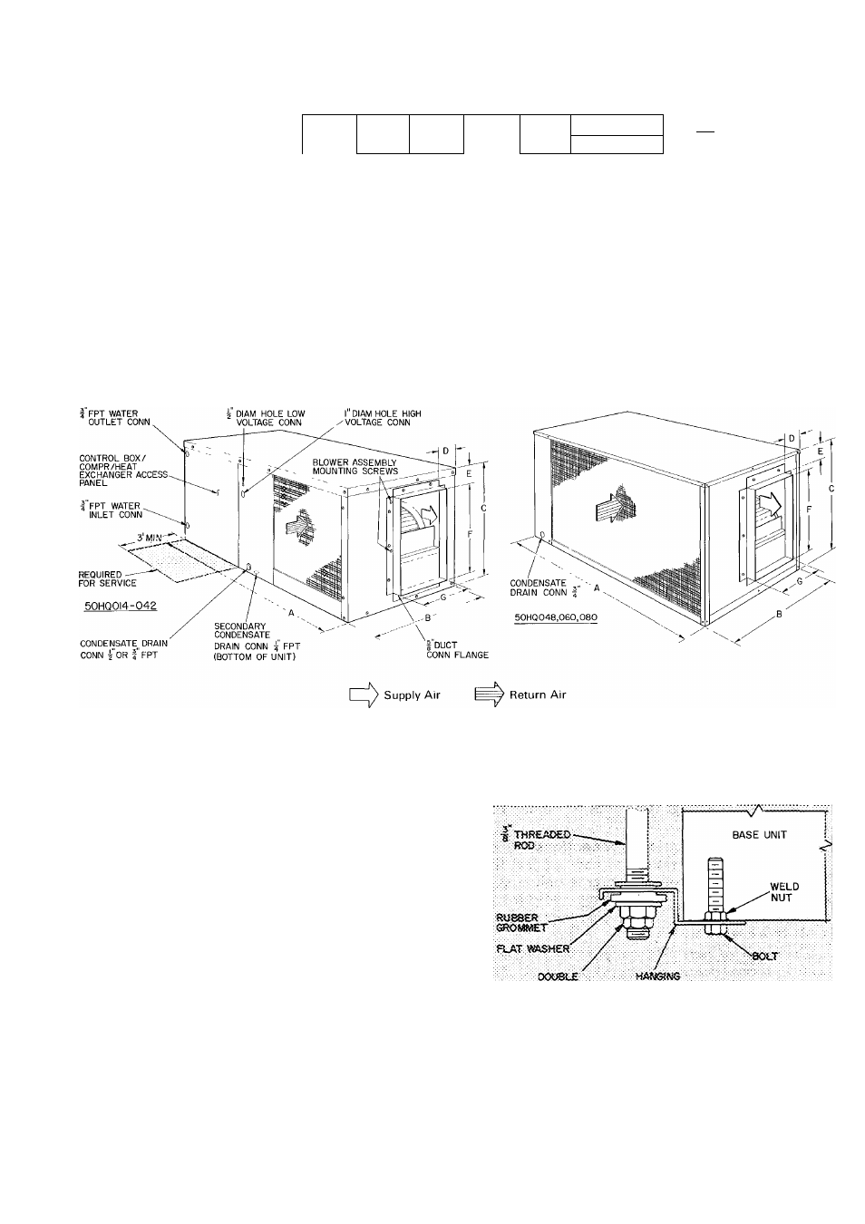
Fig. 2 — Dimensions and Connections — 50HQ
Step 3 — Make Piping Connections
CONNECT WATER SUPPLY AND RETURN
LINES to water inlet and outlet pipe connections
shown in Fig. 4 and 5. Use flexible hose for water
line to reduce possible vibration and improve unit
serviceability. Make sure hoses or pipes are suitable
for system water pressure and sized for proper
flow rate.
CAUTION;
improper
heat
exchanger
water
flow due to piping, valving or improper pump
operation is hazardous to units.
For water flow and temperature data refer to
Start-Up section, page 6.
CAUTION: Galvanized pipe or fittings are not
recommended for use with these units due
to
possible electrolysis.
nut
BRACKET
Fig. 3 — Suspension Kit
Installation — 50HQ