Selection procedure (with example), Performance data – Carrier 30HR User Manual
Page 4
Attention! The text in this document has been recognized automatically. To view the original document, you can use the "Original mode".
I Determine the unit size and operating conditions required to
meet the given capacity at the given conditions.
GIVEN;
Capacity ........................................................................................ SOTons
Leaving Chilled Water Temp (LCWT) .............................................. 44 F
Chilled Water Rise............................................................................... 10 F
Entering Condenser Water Temp .....................................................85 F
Fouling Factor (Cooler and Condenser)............................................ 0005
FOR 30HR (WATER-COOLED CONDENSER):
Enter the Ratings table marked 44 F Leaving Chilled Water
Temperature. Read down the left column (CAP ) to 80 tons
Note that either a 080 or 090 unit may be selected. Final unit
selection should be based on present and future job requirements
and the economics of the job. For this example, data from the
table is shown below for a 080 unit.
SELECTION PROCEDURE (With Example)
II Determine from Ratings table operating data for selected unit.
Unit............................................................................................... 30HR080
Saturated Discharge Temp (SDT)....................................................... 107.0 F
Compressor Motor Power input (KW).......................................... 75.9 Kw
Total Heat Rejection (THR) ....................................................101.5 Tons
Cooler Water Flow ..................................................................192.0 Gpm
Cooler Water Pressure Drop (PD).................................................. 10.7 Ft
Condenser Water Flow........................................................... 229.4 Gpm
Leaving Condenser Water Temp (Lwt)...........................................95.6 F
Condenser Water Pressure Drop (PD) ........................................... 12.0 Ft
For fouling factors other than .0005 refer to the Correction For
Fouling Factors table to: adjust the required capacity, correct
the compressor power input, and correct the actual condenser
water quantity required. ForA t (SDT — entering cond water
temp) other than 30 F, refer to curve.
FOR 30HS (CONDENSERLESS):
Use the same method, with the exception that the condenser
water data do not apply. For the remote condenser data, refer to
appropriate Carrier condenser data publication.
PERFORMANCE DATA
CORRECTIONS FOR FOULING FACTORS
Ratings are based on .0005 fouling factor in the cooler and
condenser. Correction factors for other fouling factors are given in
the following table:
CORR FACTOR
CORR FACTOR
FOULING
FOR CAPACITY
FOR
FACTOR
AND COND WATER
POWER INPUT
Cooler
Condenser
Condenser
Clean
1.01
1 02
98
.0005
1 00
1.00
1.00
.001
.98
1 03
.002
-
.94
1.10
To correct capacity, adjust as follows:
a Adjusted required capacity (use to enter table)
_______ required capacity________
cooler factor x condenser factor
b. Actual compressor power input
= compressor kw (from table) x correction factor for
power input
c. Actual condenser water quantity
= gpm (from table) x cooler factor x condenser factor
Ratings based on: 10 F chilled water rise (suitable for 5 F to
15 F rise without adjustment), .0005 fouling factor in cooler (and
condenser on model 30HR), 15 F subcooling, and R-22.
Ratings in boldface type (44 F chilled water page) are in
accordance with the latest ARI Standard 590. Conditions:
30HR — 44 F leaving chilled water temperature with 10 F rise,
95 F leaving condenser water temp with 10 F rise and .0005 fouling
factor in cooler and condenser.
30HS — 44 F leaving chilled water temperature with 10 F rise,
.0005 fouling factor in cooler, 105 F condensing temperature for
remote water-cooled or evaporative condenser, 120 F condensing
temperature for air-cooled condenser.
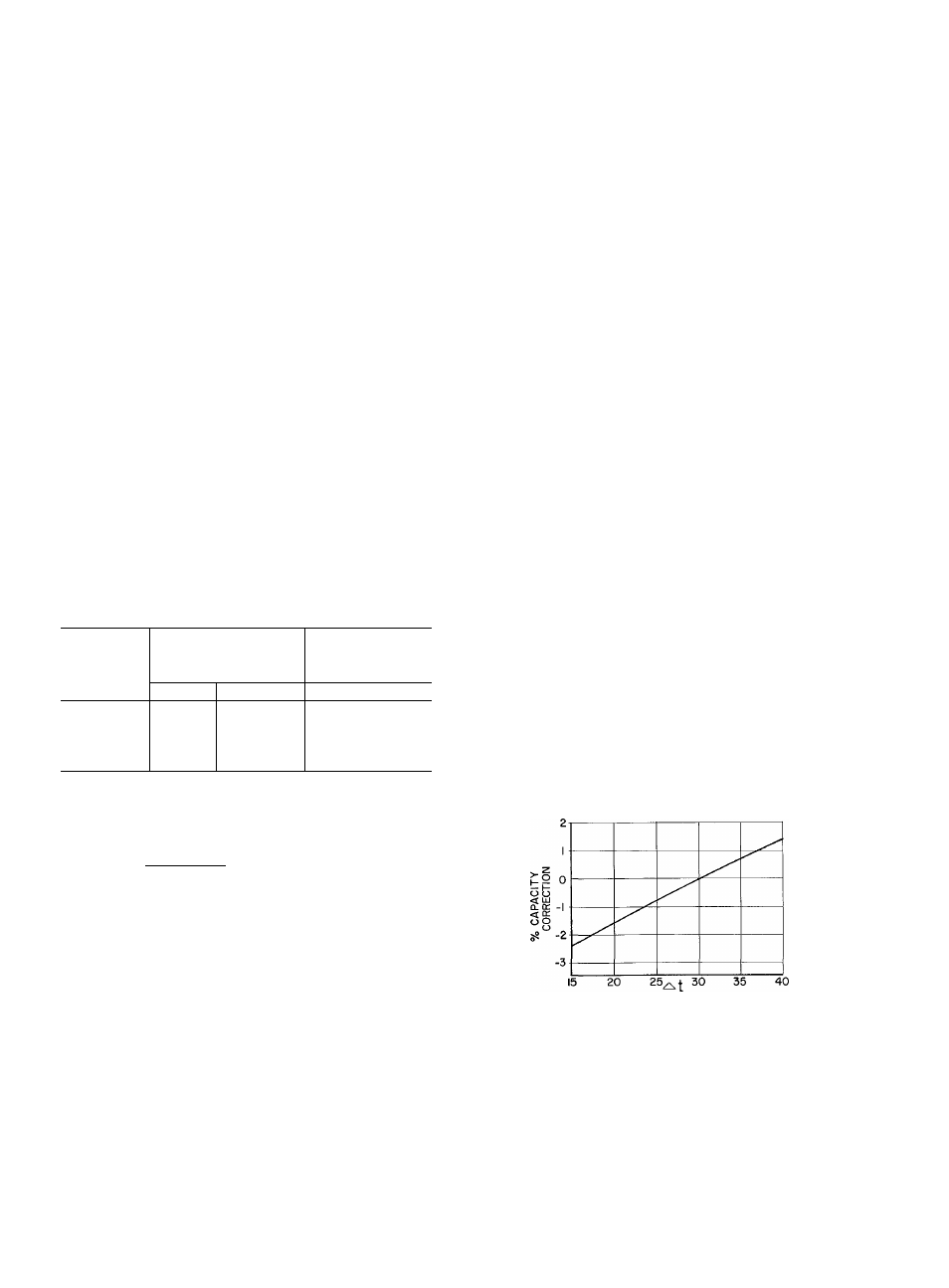
Ratings based on 15 F subcooling. On 30HR units this occurs at
30 F A t (SDT — entering condenser water temperature.) When a
30HR (water-cooled condenser) unit is selected at conditions other
than 30 F A t use the curve below to correct the ratings table
capacity.
RATINGS
The following ratings tables are for both 30HR (water-cooled
condenser) and 30HS (condenserless) models. Condenser water data
apply to model 30HR only. Ratings beyond limits shown and/or
brine ratings are available in Carrier Application Data publications.
Ratings shown for Saturated Discharge Temperature (SDT) over
120 F do not apply to model 30HR.
Correction = Ratings table capacity x percent capacity correction
(from above curve).
Above 30 F At add the correction to rating table capacity.
Below 30 F At subtract the correction from rating table capacity.
30HS units matched with remote condensers which have greater
than (less than) the 15 F subcooling in the ratings, increases
(decreases) system capacity. To adjust capacity, multiply capacity
ratings by 0,94, then adjust this result upward by 0 4 percent for
each degree F of available subcooling