Art a – Carrier 30HR User Manual
Page 18
Attention! The text in this document has been recognized automatically. To view the original document, you can use the "Original mode".
ELECTRICAL DATA (cont)
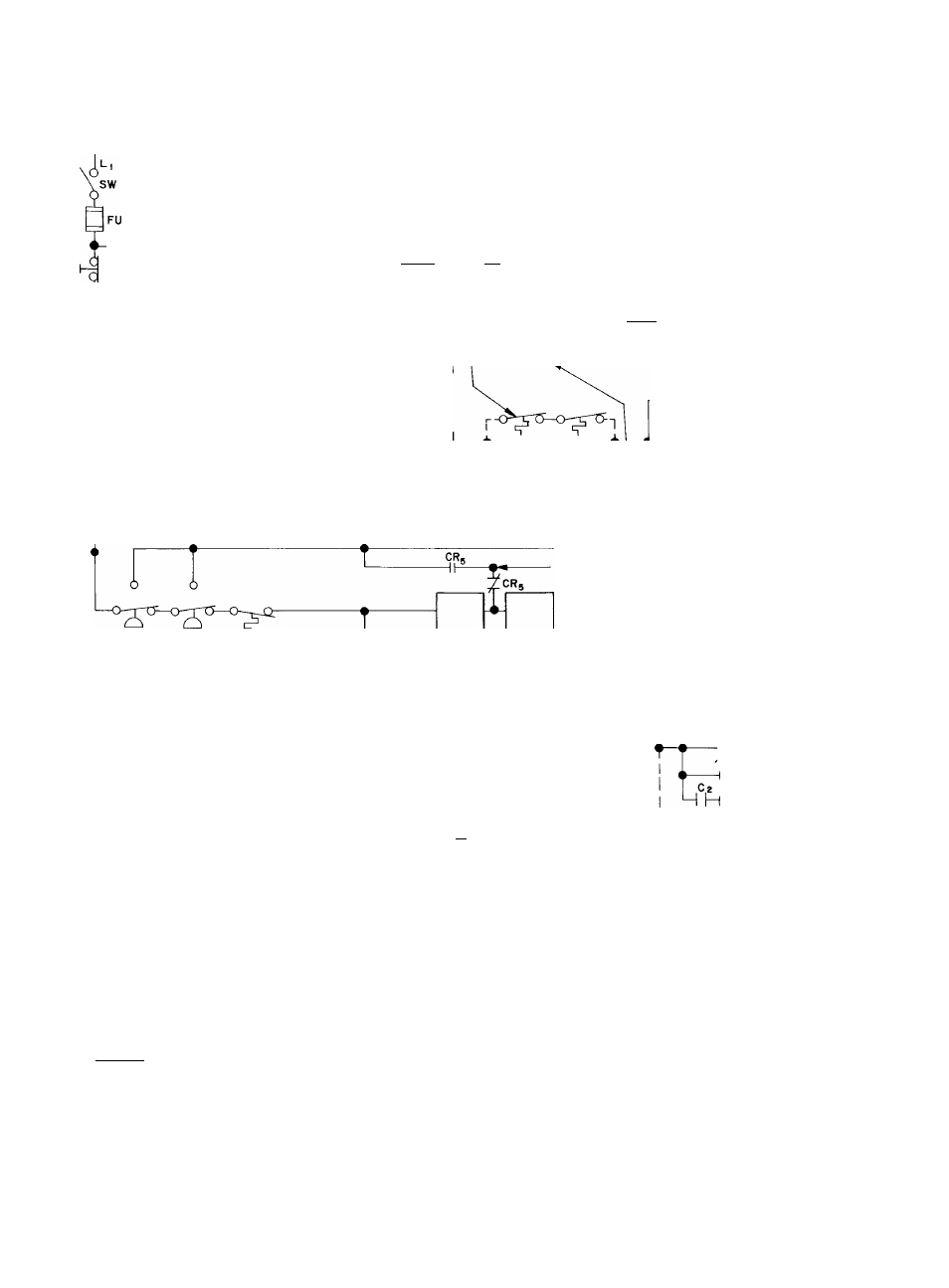
WIRING DIAGRAM; 30HR,HS070-120
CONTROL CIRCUIT
115 V, 60-HZ.
STOP BUTTON
AUX C
-VW
CH
-T-
SR
-o
FU
'^’^ART a
RESET BUTTON
^ONE ON EACH
COMPRESSOR
OPSS FACTORY
INSTALLED ON 30HS
UNITS ONLY,ONE ON EACH COMPRESSOR
CR.
COMPRESSOR I 82 IP
FU
CR,
COMPRESSOR 3 84 IP
O
lps
I
NO dUMPERS^^
WHEN OPSS
USED
¿S
l
PS
z
■FIELD-WIRED INTERLOCKS (WHEN USED)
HPSi HPS^ LWTC
LEGEND
(For diagrams pages 18 and 19)
30HR,HS070-120
30HR,HS140-160
BR
— Balancing Relay
C
— Compressor Contactor
CA
— Second Contactor
CB
— Circuit Breaker
CH
— Crankcase Heater
COMPR
— Compressor
CR
— Control Relay
CS4
— On-Off Switch, Compressor 4
FU
— Fuse
HPS
— High Pressure Switch
IP
— Internal Motor Protection
(Thermotector)
LLS
— Liquid Line Solenoid Vaive
LPS
— Low Pressure Switch
LWTC
— Low Water Temperature Cuto
OPSS
— Oil Pressure Safety Switch
RR
— Recycie Relay
SM
— Sensor Module
(solid state compr motor prot
SR
— Starting Relay
SW
— Switch (start-stop)
TM
— Timer Motor
TR
— Timer Relay
U
— Unloader (compressor)
Factory Wiring
__
Factory Wiring, 30HS only
o
Coil
H
Contacts Normally Closed
11
Contacts Normally Open
;®:
Light (Red)
FI ELD-INSTALLED AUXILIARY
EQUIPMENT TERMINALS
T \
m
5'
-----“-------
r r
LLS,
CR,
C^
CR,
-SEQUENCE
TRANSFER
MOTOR
MULTIPLE-
STEP
CONTROLLER
BR
a
RR
X
24V
LLS,
X-
(?)—
1
__
--CHt5--------------
OPSS 2
-©------------
-w-
-X
I^TEMPERATURE
CONTROLLER
J"EMPERATURE
SENSING BULB
H@------------
—
- o r p -
OPSS,
prY>~l
TRANSFORMER
II5V __________________