Guide specifications – Carrier 30HR User Manual
Page 20
Attention! The text in this document has been recognized automatically. To view the original document, you can use the "Original mode".
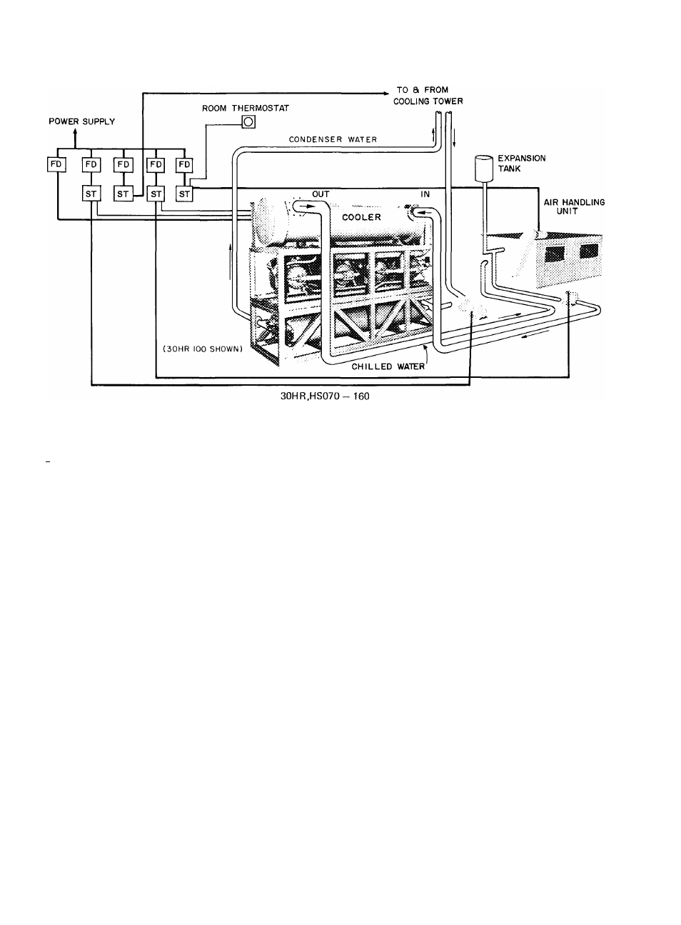
TYPICAL PIPING AND WIRING
FD
— Fused Disconnect
ST
— Starter
mmmmm
Power Wiring
--------- Control Wiring
n !>
Piping
NOTES:
1. Wiring and piping shown are general points-of-connection guides only and are not intended to be used,
or to include all details, for a specific installation
2 All wiring must comply with applicable local and national codes
3 All piping must follow standard piping techniques Refer to Carrier System Design Manual for details.
Furnish
and
Install
„
.factory-assembled
30HR
water-cooled
(30HS
air-
or
evaporative-cooled)
multiple
hermetic
compressor
liquid
chilling
package(s)
with
a
capacity
of
.tons
using
Refrigerant
22
Unit
shall
cool
gpm
of
water
from
_
F
to
F,with. . gpm of condenser water entering at . For
when operating at
F saturated discharge temperature Fouling
factor shall be _ in cooler and _ _ in condenser Cooler water
pressure
drop
shall
not
exceed
_
ft
Condenser
water
pressure
drop shall not exceed „ft
Construction and Ratings
shall be in accordance with lastest ARI
Standard
590
and
shall
comply
with
USAS
B9
1
safety
code.
National Electrical Code, and applicable ASME Code
Compressors
shall
be
reciprocating,
serviceable,
hermetic
type,
and shall have an automatically reversible oil pump and an operating
oil
charge
Compressors
shall
be
equipped
with
suction
and
discharge shutoff valves, and shall be mounted on spring vibration
isolators
Each
compressor
motor
shall
be
cooled
by
suction
gas
passing
around
the
motor
windings
and
shall
have
thermal
pro
tectors embedded in the windings Manual restart of unit shall be
required
after
motor
stoppage
due
to
thermal
overload
Each
compressor shall be equipped with an insert-type crankcase heater
to control oil dilution during shutdown
For each compressor there shall be a factory-installed contactor
and a calibrated
manual
reset, ambient
Insensitive magnetic circuit
breaker The circuit breakers shall open all three phases should an
overload occur on any phase
Cooler
shall
be
shell-and-tube
type,
with
removable
heads;
it
shall have two direct expansion refrigerant circuits Seamless 1/2-in
OD copper tubes shall be rolled into the tube sheets Shell shall be
covered
with
1-in
layer
of
closed-cell
foam
plastic,
vapor
barrier
insulation
Each Refrigerant Circuit
shall include: hot gas muffler; com
bination
moisture
indicator
and
sight
glass;
refrigerant
filter-drier;
liquid line solenoid valve; thermal expansion valve; charging valve.
GUIDE SPECIFICATIONS
All
suction
lines
shall
be
insulated
with
close-fitting
cellular
insulation Condenserless units shall have discharge line check valves
furnished for installations using remote condensers
Water-Cooled Condensers
(2 per unit) shall be shell-and-tube
type
with
integral-finned
copper
tubes,
and
shall
have
removable
heads
Construction
shall
comply
with
applicable
ASME
code Each
condenser shall be constructed to provide positive subcooling of the
liquid refrigerant A pressure relief valve, purge cock and a liquid
shutoff valve shall be provided on each condenser
Unit
shall
have
a
control
box
which
contains
high
and
low
pressure cutout switches for each refrigerant circuit; a manual reset
low
water
temperature
cutout
switch;
a
multiple-step
chilled
water
temperature
controller
to
ensure
staggered
starting
of
compressors
and to provide _ ..steps of capacity control
Mounted on control box of 30HS units, as standard equipment,
shall be
an
oil pressure safety switch for each compressor The
control panel shall have mounted on it a control power indicator
light,
individual
compressor
indicator
lights;
a
START-STOP
button
(switch); control power fuses (circuit breaker); a manual switch to
change starting sequence of compressors from one refrigerant circuit
to the other, and (except for 30HR ,HS040,050,060 units) a suction
pressure gage and a discharge pressure gage for each refrigerant
circuit
Unit shall operate on volt, phase, . Hz power It
shall be capable of operating within line voltage limits of _____________________
to . volts Control power shall be 115
V ,
60-Hz
Maximum Dimensions of Unit
shall be length .width
, height
Accessories
available for all size units shall include: oil-pressure
safety
switches
(HR
only),
control
circuit
transformer;
chilled
water
flow
switch;
insulated
enclosure
panels
For
all
sizes
except
30HR160:
condenser
water
manifold
package
For
30HR,HS040,
050,060 units only: two gage panels, each with a suction and a dis
charge pressure gage
C A R R I E R
Tab 15
Manufacturer reserves the right to change any product specifications without notice.
A I R C O N D I T I O N I N G C O M P A N Y • S Y R A C U S E ,
Form ЗОНR,HS-5P
Printed in U S A
Supersedes ЗОНR ,HS-4P, ЗОНR,HS-1 GS
6-69
Codes C and MA
N E W Y O R K
Catalog No 523-013