Carrier 30HR User Manual
Page 17
Attention! The text in this document has been recognized automatically. To view the original document, you can use the "Original mode".
ELECTRICAL DATA (cont)
GENERAL NOTES
1. Compressor models 1 50, 250 and 266 are 4-cyl; 275 and 299 are
6-cyl.
2
Max incoming wire size for 208, 230 volts Two- and three
compressor units have one terminal block, 3 wires, 350 MCM for
040-060, 500 MCM for 070-090 Four-compressor units have
two terminal blocks, 3 wires per block; 350 MCM for 100-120,
500 MCM for 140, 160
3
Max incoming wire size for 460, 575 volts; All units have one
terminal block, 3 wires; 0000 for 040-060, 350 MCM for
070-120, 500 MCM for 140, 160
4 Across-the-line start is standard for all units at all voltages To
obtain part-winding start, make following modifications
208-230 volts —
All units (040 thru 160) all compressors are factory wired thru
two contactors Add 1 5-second time delay relay for each
compressor, to actuate second contactor
460,575 volts —
30HR,HS040 thru 120: Add second contactor and 1 5-second
time delay relay for each compressor in unit
30FIR,HS140: Add second contactors for no 2 and no 4
compressors: add 1 5-second time delay relay for each com
pressor in unit
30HR,FIS160:
All
compressors
are
factory
wired
thru
two
contactors; add 1 5-second
time
delay relay
tor
each
compressor
in unit
5
On units 140 and 160, a manual switch is provided to cut no. 4
compressor out of the system during intermediate seasons to
reduce demand load
STARTING SEQUENCE TRANSFER
UNIT 30HR,HS
040-060
j
070-090 1 100-120 | 140,160
Switch Pos
Compressor Starting Sequence
1
1-2 1 3-2-1 1 1-4-3-2 1 1-3-2-4
2
2-1 j 1-2-3 1 3-2-1-423-1-4-2
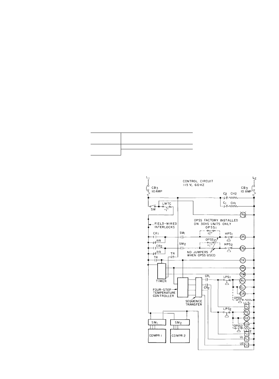
WIRING DIAGRAM, 30HR,HS040,050,060
LEGEND
C
— Compressor Contactor
CA
— Second Contactor
CB
— Circuit Breaker
CH
— Crankcase Heater
COMPR
—
Compressor
CR
— Control Relay
HPS
— High Pressure Switch
LLS
— Liquid Line Solenoid Valve
LPS
— Low Pressure Switch
LWTC
— Low Water Temperature Cutout
OPSS
— Oil Pressure Safety Switch
RR
— Recycle Relay
SM
— Sensor Module
(solid state compressor motor protection)
SW
— Switch (start-stop)
TM
— Timer Motor
TR
— Timer Relay
U
— Unloader (compressor)
_______ Factory Wiring
_______ Factory Wiring, 30HS only
0
Coil
Tl
Contacts Normally
Closed
1
I
Contacts Normally
Open
z®;
Light (Red)
17