Table 4 — setting safety controls (contd), Setting operating controls — electronic, Pressure – Carrier 19CB User Manual
Page 9: R- vl
Attention! The text in this document has been recognized automatically. To view the original document, you can use the "Original mode".
SAFETY OR CONTROL DEVICE
Table 4 — Setting Safety Controls (contd)
SAFETY OR CONTROL DEVICE
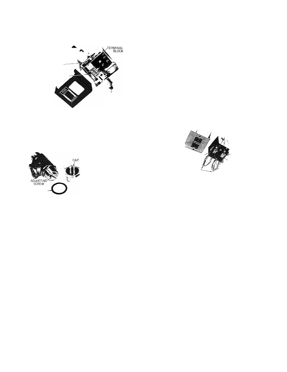
5. Low Oil Pressure Cutout (Fig, 2)
RESERVOIR
PRESSURE-:^,
RANGE
^
DIAL ADJUSTMENT,
REMOVE METAL
COVER
DIFFERENTIAL-
OIL
PRESSURE
Low oil differential pressure switch is factory set to open at 5 5 ± 1
psi and close at 12 5 ± 1 psi differential pressure Operate oil pump
manually Remove cap and gasket from regulating valve and loosen
locknut
Turn
adjusting
screw
counterclockwise
to
lower
oil
pressure to 5 psi differential If safety does not trip, turn range dial
clockwise until cutout occurs
6. Oil-Pressure Regulating Valve (Item 6, Fig
2
) .
REFRIG
^ R- Vl.
R-114
SETTING*
1 5 psid
15-20 psid
^Settings given are above
reservoir pressure
SEALING
GASKET'
Remove cap and washer and loosen locknut Turn adjusting screw
clockwise to raise oil pressure
7. Vane Speed Valve (Electronic Machine Only)
Angle valve is located between oil line to main bearing and "F" and
"G" solenoid valves (Items 8 and 9, Fig 2) Set valve at full open
position
8. Chilled Water Flow Switch
Field
supplied
and
ir-rstalled
Follow
switch
manufacturer's
instruc
tions for adjustment and maintenance
9. Main Bearing Oil Temperature (Item 14, Fig. 2).
During
machine
operation,
gage
should
read
145-160
F
Adjust
water flow thnr oil cooler with plug cock (item 11, Fig. 2) Do not
exceed 7 gpm or pressure drop of 5 psi Do not exceed 200 psig
working pressure
10.
Dual Pressurestat for R-114 Pump-Down Compressor
COVER
LOW-PRESSURE
SWITCH
COMPRESSOR
CONNECTIONS'
CUTOUT AND
CUT-IN PRESSURE
ADJUSTMENT
HIGH-
PRESSURE
SWITCH
CUT-IN
PRESSURE
'ADJUSTMENT ONLY
CUTOUT PRESSURE
ADJUSTMENT ONLY
High-pressure switch to open on rise at 45 0 psig Low-pressure
switch to open on fall at 2 0 in Hg vacuum
Set
high-pressure
switch
by
operating
compressor
and
throttling
pump-down condenser water while watching pressure gage
Set
low-pressure
switch
by
operating
compressor
and
gradually
shutting suction valve while watching pressure gage
Setting Operating Controls — Electronic
MOTOR CURRENT CATIBRATION (Electronic
Capacity Control)
1. Establish a steady motor current value for this
calibration.
Open
guide
vanes
manually
(capacity control to “Inc”) until full load
current is reached. Motor current calibration
(Fig. 7) may need to be turned counterclock
wise to permit vanes to open further. Do not
exceed 105% of nameplate full load amperes.
If system load is sufficient to maintain full
load current for a period of time, calibrate at
this condition. With small loads, pull down to
and maintain design leaving chilled water
temperature (capacity control at “Hold”) and
calibrate at this condition.
2. Measure motor current at selected condition.
Determine its percentage of full load motor
current.
3. Use this percentage figure to set the electrical
demand adjustment (Fig. 7) per the following
table:
Percent of Full
Load Motor Current
105
85 or above
65 to 84
45 to 64
below 45
Electrical Demand
Adjustment Setting
100
%
80%
60%
40%
Control cannot be
calibrated
4. Turn the motor current cahbration adjustment
fully clockwise. The guide vanes will close part
way.
5. Turn the thermostat adjustment (Fig. 7) to
“Cooler” (fully counterclockwise).
6. Set capacity control at “Inc
7
position.
Slowly turn the motor current calibration
counterclockwise. Allow the guide vanes to
open until motor current reaches 5% above the
electrical demand setting.
NOTE: There is a time lag of several seconds
due to feedback capacitance in the motor
current circuit. When the motor current cali
bration setting is adjusted, allow for this time
lag.