Refrigerant charge – Carrier 19CB User Manual
Page 5
Attention! The text in this document has been recognized automatically. To view the original document, you can use the "Original mode".
r.
Refrigerant Charge
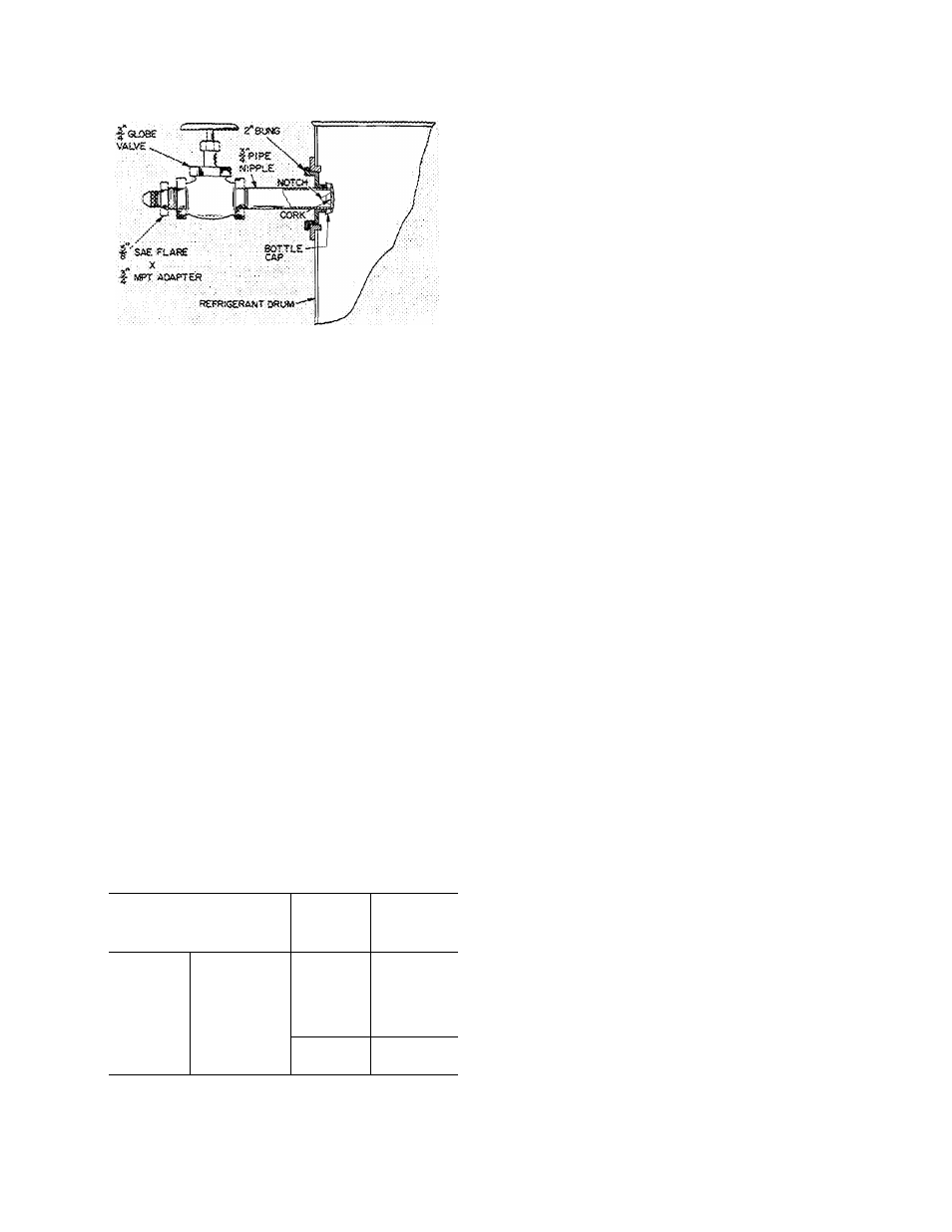
1. Install a charging valve in the 3/4-in. drum
opening as shown in Fig. 5.
3.
4.
Fig. 5 — Drum Charging Valve
Connect a short length of plastic hose or copper
tubing from drum valve to cooler charging
valve.
Circulate chilled water during the charging
process.
At a pressure less than that indicated in Table
2, liquid refrigerant will flash into gas and may
cause tube freeze-up. Keep refrigerant drum
upright and admit refrigerant as a gas until
cooler pressure is greater (smaller value of in. of
mercury vacuum) than that listed in Table 2.
Table 2 — Pressures Corresponding to 32 F
Saturation Temperature
REFRIGERANT
R-11
R-114
PRESSURE - INCHES
OF MERCURY VACUUM
18 05
3 85
5 The refrigerant supplied with the machine is in
excess of the amount required for initial charg
ing. Charge the amount shown in Table 3, less
200 pounds
6. After the machine has been started, it may be
necessary to adjust the charge for optimum
machine performance. For this adjustment, see
Trimming Refrigerant Charge.
Table 3 — Refrigerant Shipping Charges
MACHINE SIZE
Model Heat Exch
No.
^
Combn*
REFRIG
SHIPPING
CHARGE
19CB1200
19CB33-36
R-11
3200
19CB1300
19CB33-36
R-11
3200
19CB1400
19CB43-46
R-11
3750
19CB1500
19CB53-56
R-11
3750
19CB1600
19CB64-66
R-11
4000
19CB1800
19CB77-78
R-114
5400
19CB2000
19CB87-88
R-114
5400
*First 6 digits of 1 0-digit Machine Model code
Inspect Piping
Refer to piping diagrams provided in Job Data
and inspect piping to cooler, condenser and oil
cooler.
Chilled water should enter the lower nozzle of
the cooler and leave at the upper nozzle. Chilled
water temperature probe should be installed in
leaving chilled water hue.
Condenser water should enter the upper con
denser nozzle and leave at the lower.
Insure that pipes are vented and properly
suspended, with no stress on nozzles or on water
box covers.
Check to see that water flow agrees with design
flow. Pressure drop measurements across cooler
and condenser or across the pumps will indicate
approximate flow rate.
Oil cooler water must be clean, with 85 F
maximum temperature and 200 psi maximum inlet
pressure. Refer to tag attached to the inlet line for
pressure drop and velocity limits.
Field Wiring
WARNING: Do not attempt to check high
voltage supply without proper equipment.
Serious personal injury' cajr result.
Refer to Job Data wiring diagrams and check
field wiring as follows:
1. Connect voltmeter across incoming power wires
to compressor motor starter. Compare the
reading with voltage ratings on compressor and
starter nameplates.
2. Check that amperage rating on starter name
plate matches full load amperage rating on
compressor motor nameplate.
3. Ensure that voltage to oil pump starter agrees
with oil pump nameplate value.
4. Ensure that pumpout compressor voltage ^sup
ply agrees with motor nameplate.
5. Check that electrical supply to purge pump
(R-11) is 120 volts.
6. Test compressor motor and motor power lead
insulation resistance with a 500 volt insulation
tester such as a megohmmeter.
a Open starter nmin disconnect switch.
b. With tester connected to the motor side of
the starter contactor in the starter, take
60-second and 10-second megohm readings
as follows’
Six lead motor — Tie all 6 terminals together
and test between terminal group and ground.
Next, tie terminals in pairs, 1 and 4, 2 and 5,
3 and 6. Test between each pair while
grounding the third pair.
Three lead motor — Tie terminals 1,2 and 3
together. Test between terminal group and
ground.
c. Divide the 60-second resistance reading by
the 10-second reading. This ratio, or polar
ization index, must be 1.15:1 or higher.
Both the 10-second and 60-second reading
must be at least 5.0 megohms. If the
readings are unsatisfactory, repeat the test
at the motor terminals with power leads
disconnected. Satisfactory readings in this
second test indicate that the fault is in the
motor leads.