Carrier 19CB User Manual
Page 4
Attention! The text in this document has been recognized automatically. To view the original document, you can use the "Original mode".
SEPARABLE UNION
PIPING BY CARRIER
FIELD PIPING
1. Connect dehydration pump to cooler charging
valve.
2. Ensure that all valves on purge assembly are
closed; valves on filter-drier system open.
3. Install mercury manometer (absolute pressure
type) at charging valve.
4. Operate pump until manometer reads 0.20 in.
Hg absolute. Continue to operate pump for 2
more hours.
5. Close cooler charging valve; stop pump; record
manometer reading.
6. Wait 2 hours and read manometer again. If ab
solute pressure reading has not increased, dehy
dration is complete. If absolute pressure has
increased, repeat steps 4, 5 and 6.
7. If vacuum fails to hold after several dehy
dration attempts, check for machine leak by
repeating the (?heck for Small Leaks.
Pumpout Procedures
(R-114 Units)
MACHINE EVACUATION (No refrigerant in
system)
1. Set purge valves per Operation 5 on purge valve
operation plate.
2.
Jumper low-pressure cutout on pumpout
compressor.
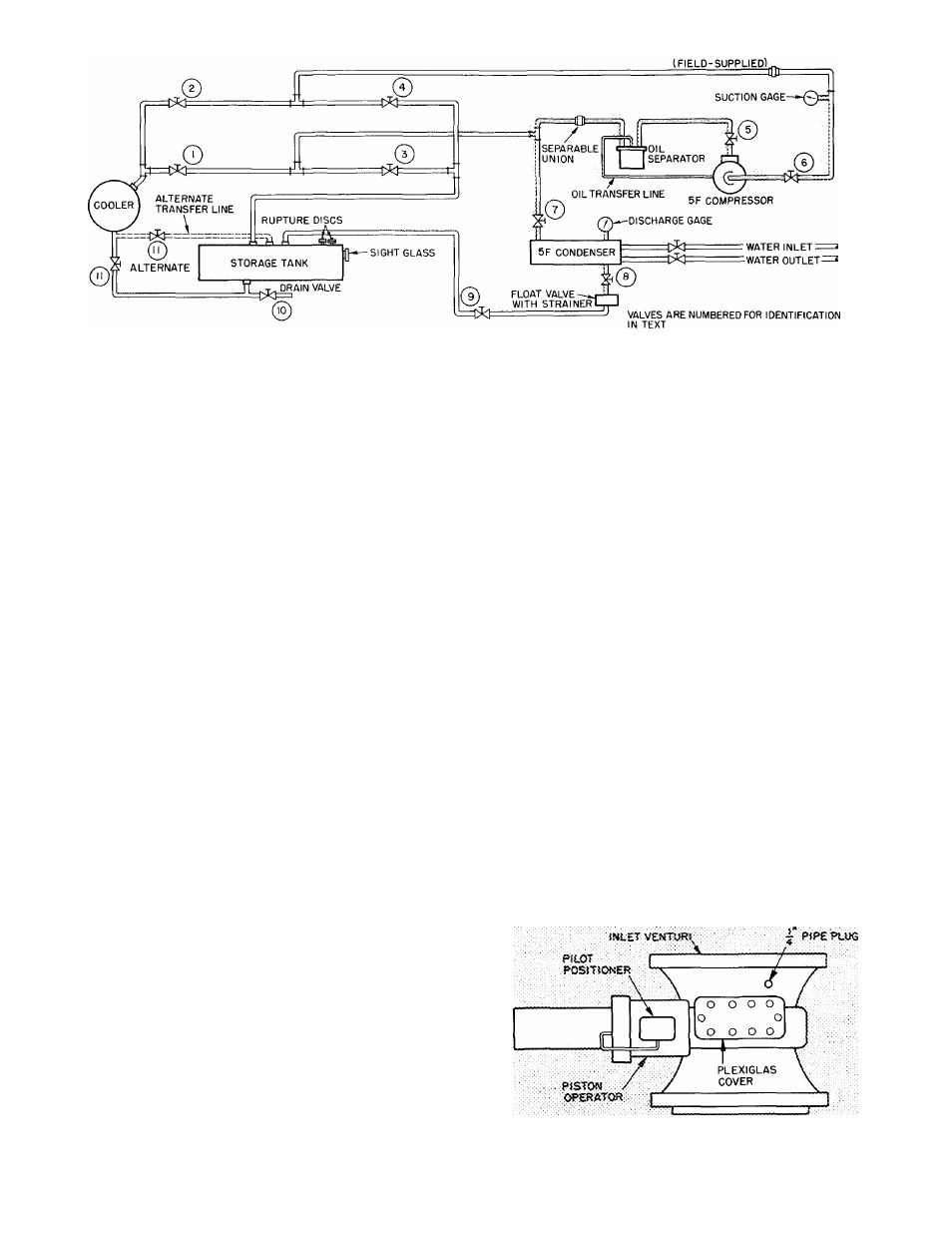
3. Close valves 1, 3, 7 and 10.
4. Open valves 2, 4, 5, 6, 8, 9 and 11
5. Disconnect separable union between pumpout
condenser and oil separator.
6.
Run
pumpout
compressor
until
desired
machine vacuum is reached.
7. Close valve 5 and reassemble union.
8. Stop compressor.
9. Remove jumper.
PRESSURIZING THE MACHINE (No refrigerant
in system)
1. Set purge valves per Operation 4 on purge valve
operation plate.
2. Close valves 2, 4 and 10.
3. Open valves 1, 3, 5, 6, 7, 8, 9 and 1 1.
4. Disconnect separable union in pumpout com
pressor suction Hne.
Fig. 3 — Pumpout System Schematic (R-114 Units)
5. Operate pumpout compressor until desired
pressure is reached. Do not exceed test pressure
listed in Table 1.
6. Shut off pumpout compressor
7. Reassemble union.
8. Return purge valves to “Normal-Auto” condi
tion when pressurizing is completed.
Oil Charge
— Use oil shipped with machine. This
oil conforms to Carrier’s oil specifications for
hermetic centrifugal compressors.
Charge oil thru the oil reservoir charging valve.
Machine vacuum will draw the oil from the
container. Add oil until it reaches the middle of
the oil sight glass. After charging, close valve
completely to prevent air from entering machine.
R-114 machines containing refrigerant will require
a small hand pump for oil charging.
On pneumatic machines, add oil to the vane seal
chamber thru pipe plug opening (see Fig. 4) until
level reaches bottom of rack and gear as seen thru
Plexiglas cover.
Oil Heater
— Check for 1 20 volt supply. Energize
oil heater to minimize oil-refrigerant absorption. A
light indicates when the heater is energized. The oil
heater thermostat is set to maintain a temperature
of 140 F ± 3 F at shutdown. Adjust if required.
Fig. 4 — Pneumatic Vane Shaft Seal Chamber