Carrier 19CB User Manual
Page 11
Attention! The text in this document has been recognized automatically. To view the original document, you can use the "Original mode".
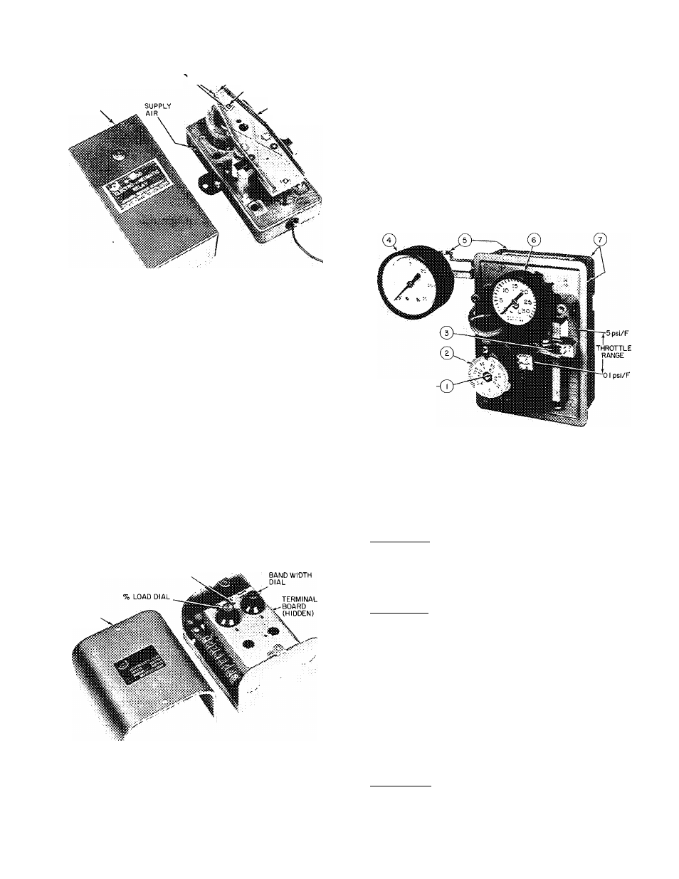
ELECTRO-PNEUMATIC RELAY
LOCKNUTS
SENSITIVITY SCREW
^SET POINT SCREW
COVER
CONTROL AIR
(OUTPUT)
This control is factory calibrated to provide a
linear output signal of 3 psi at 6 volts d-c to 18 psi
at 15 volts d-c. Field recaHbration should not be
necessary.
If calibration is required:
1. Establish 15 volt d-c input with 25 psi supply air.
2. Turn sensitivity screw to obtain 18 psi or higher
output.
3. Adjust setpoint screw, if required, to set output
at \ 8 ±V4 psi.
4. Reduce input to 6 volts. Output should be 3 ±
V4 psi. If low, turn sensitivity screw carefully
clockwise. If high, turn screw counterclockwise.
5. Recheck output at 15 volts. Repeat steps 3 and
4 if necessary.
DEMAND LIMIT CONTROL
CALIBRATION
ADJUSTMENT
COVER
1. Set percent load dial at 100%.
2. Set band width dial at 3.
3. Turn the cahbration adjustment screw fully
clockwise.
4. Run machine at 100% FLA by adjusting dial on
chilled water thermostat.
5.
Turn calibration adjustment screw counter
clockwise until guide vanes just begin to close.
6. If hunting occurs, increase bandwidth and re
peat steps 4 and 5.
7.
If control cannot be calibrated with above
procedure, check voltage signal from resistor in
starter. At 100% full load, voltage between
termmals 23 and 24 inside control center must
be 3.0 ± 0.1 volts. If not in this range, check siz
ing of resistor in starter.
CHILLED WATER THERMOSTAT (Pneumatic)
HIDDEN
ITEM
1
2
3
4
5
6
7
DESCRIPTION
SET POINT ADJUSTING SCREW
THERMOSTAT DIAL
SENSITIVITY SLIDER
SUPPLY AIR PRESSURE GAGE
SUPPLY AIR CONNECTIONS
CONTROL AIR PRESSURE GAGE
CONTROL AIR CONNECTIONS
Preparation:
1. Ensure 25 psi supply air to thermostat.
2. Loosen Allen setscrew in sensitivity slider and
move slider halfway between midpoint and DA.
Retighten screw.
Calibration:
1. Turn thermostat dial until control air registers
15 psi.
2. Operate machine to reach design chilled water
temperature at design load. Maintain 15 psi
control air during pulldown by adjusting ther
mostat dial as required.
3. On reaching design chilled water temperature,
turn dial until control air pressure holds
machine at design conditions.
4. Hold set-point adjusting screw stationary within
the dial post and set the thermostat dial at de
sign chilled water temperature.
Completion:
If vane hunting occurs, move sensitivity slider
away from DA. Throttle range may be narrowed or
widened by moving slider between the limits of 0.1
psi/F at midpoint to 5 psi/F at DA.
11