Indoor air fan pulley alignment and adjustment – Carrier 48EL User Manual
Page 9
Attention! The text in this document has been recognized automatically. To view the original document, you can use the "Original mode".
#
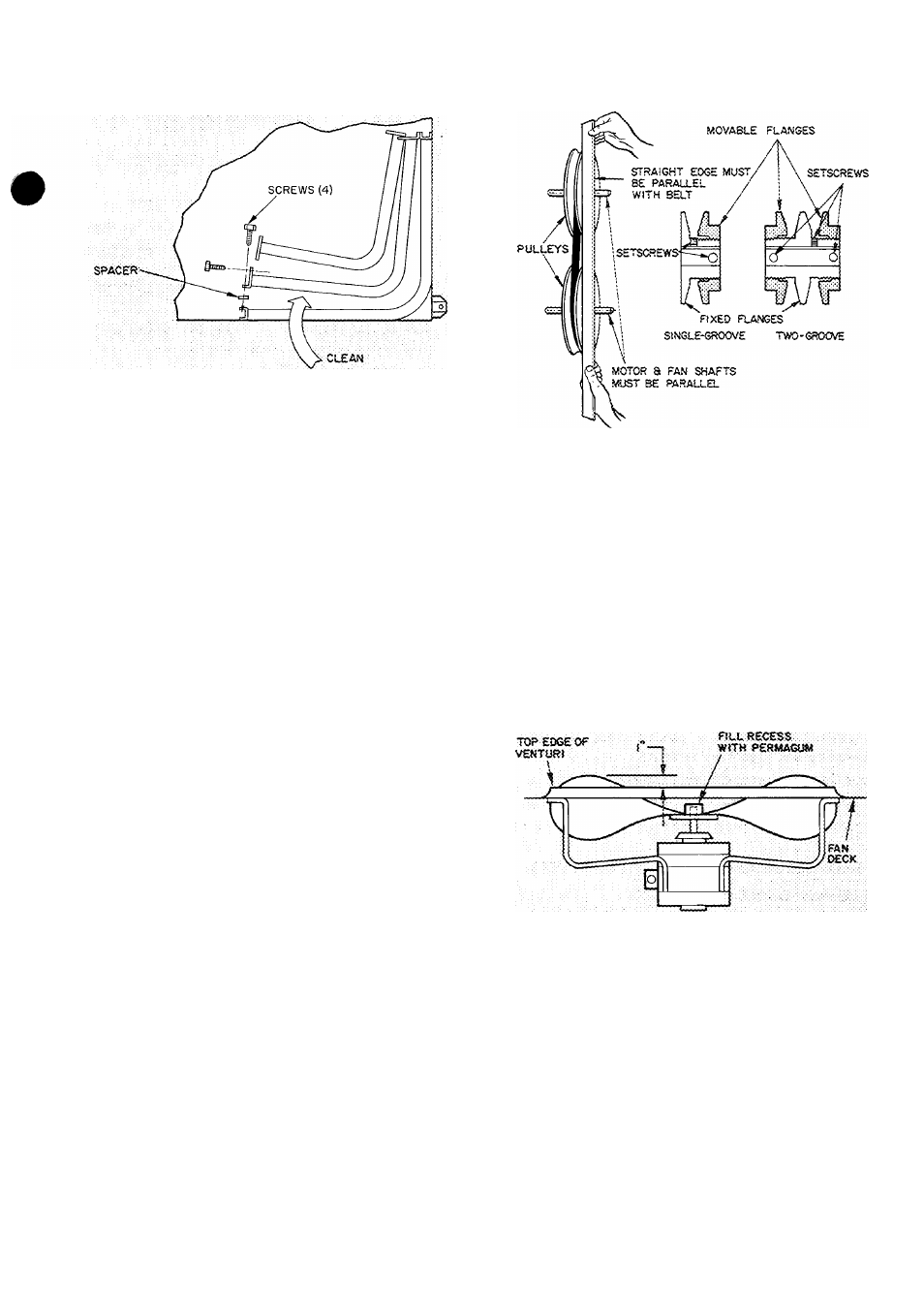
Fig. 9 — Outdoor Coil Cleaning
4.
5.
6
Using a water hose, or other suitable equip
ment, flush down between the 3 sections of the
condenser coil to remove dirt and debris.
Clean the remaining surfaces in the normal
manner.
Reposition the inner coil sections. Reinstall the
screws in the tube sheet and replace the top
cover.
CONDENSATE PAN AND DRAIN LINES - Clean
once a year, preferably in the spring. Drain off
water in the fall and keep trap dry or protect from
freeze-up thru the winter.
FILTERS — Inspect filters at start of each heating
and cooling season and as often during each season
as conditions warrant. Clean permanent filters per
manufacturer’s instructions. Throwaway filters
may be cleaned by vacuum or by tapping lightly
over newspaper. Replace filters with the cleaner
side facing downstream. After one cleaning, replace
throwaway filter.
INDOOR FAN ADJUSTMENT - Fan motor
pulley is factory set for speed shown in Table 1. To
change fan speed:
1. Shut off unit power supply.
Slide fan housing from unit.
Loosen fan belt by loosening fan motor
mounting plate bolts.
Loosen movable pulley flange setscrew (see
Fig. 10).
Screw movable flange toward fixed flange to
increase speed and away from fixed flange to
decrease speed. Increasing fan speed increases
load on motor. Do not exceed maximum fan as
specified in Table 1.
Set movable flange at nearest key way of pulley
hub and tighten setscrew.
To align fan and motor pulleys, loosen fan
pulley setscrews and slide fan pulley along fan
shaft. Make angular alignment by loosening motor
from mounting plate (see Fig. 10).
2
.
3.
4.
5.
6
.
Fig. 10
Indoor Air Fan Pulley Alignment
and Adjustment
To Adjust Belt Tension — Loosen fan motor pivot
bolts. Move motor mounting plate for proper belt
tension (1/2-in. deflection with one finger) and
tighten pivot bolts. Adjust lock bolt and nut on
mounting plate to secure in fixed position.
OUTDOOR FAN ADJUSTMENT ^ The required
fan position is shown in Fig. 11. Loosen setscrews,
set fan at dimension indicated and retighten.
Fig. 11 — Outdoor Fan Clearance
Adjusting Spark Ignition — If pilot fails to ignite,
check the spark ignition system as follows:
1. Shut off power to ignitor.
2. Check that spark gap is .12 inch. (See Fig. 7.)
3. Make sure that spark generator is .securely
grounded.
4. Check that high-voltage lead is securely con
nected between generator and electrode body.
5. Restore power. Check for 24-volt supply to
primary side of generator.