Carrier 48EL User Manual
Page 4
Attention! The text in this document has been recognized automatically. To view the original document, you can use the "Original mode".
5.
7.
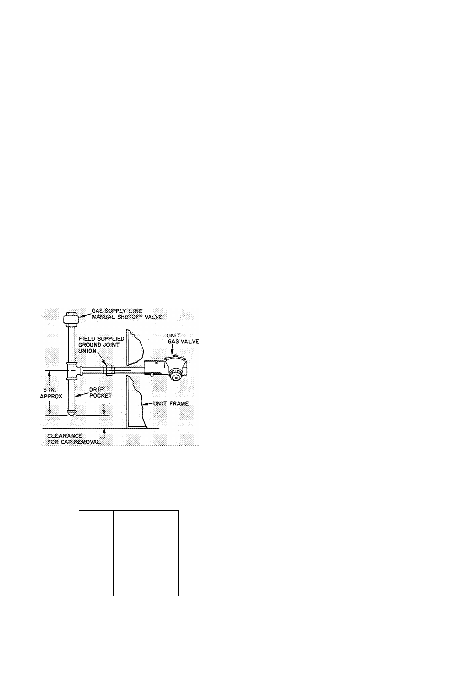
Pitch all horizontal pipe runs towards the unit
1 /4-in. per 15 ft to prevent trapping condensed
moisture.
Support piping to maintain proper pitch,
prevent strain on unit controls, and prevent
accidental movement of piping.
Install a tee for attachment of a dirt and
moisture drip pocket (Fig. 4). Tee should be at
same level or below gas valve connection. Drip
pocket must be protected against freeze-up
Install manual shutoff valve on gas piping per
local codes.
8. Provide a ground joint union in the gas supply
line near the unit gas valve.
9. Protect gas piping from freezing temperatures
Gas stoppage can result from failure to insulate
pipe against wide or sudden temperature
changes.
10. When piping is completed, check entire gas
assembly and field piping with soap and water
solution.
Never use an open flame for leak testing.
NOTE Connection to unit gas valve is 1/2 in FPT
Fig. 4 — Gas Piping Details
Table 2 — Maximum Pipe Cap. (cfh)*
PIPE
LENGTH (ft)
NOMINAL PIPE SIZE (in.)
1/2
3/4
1
1-1/4
10
132
278
520
1050
20
92
190
350
730
30
73
152
285
590
40
63
130
245
500
50
56
115
215
440
60
—
105
195
400
70
—
96
180
370
80
—
90
170
350
90
—
84
160
320
100
—
79
150
305
*Cfh — Cu ft/hr based on 0 3 in wg pressure drop and 0.6
gas specific gravity
NOTE: Correction is not necessary for normal number of
fittings nor for 0.7 gas specific gravity unless specified
Drain Piping — The condensate drain connection
(3/4-in. MPT) is on service access face of unit
(Fig. 1). Since drain is on the suction side of the
indoor (evaporator) fan, it must be trapped to
prevent leakage back into the unit. Trap should be
at least 3 in. deep and should be formed of flexible
material or in such a manner as to resist freeze-up
damage.
Wiring — The design center voltage for each unit is
stamped on the unit nameplate. The supply voltage
at the unit must be within maximum and minimum
limits shown on nameplate and in Tabled. Phase
unbalance on 3-phase units must be within 2%.
Contact local power company if correction is
necessary. Operation of the unit on improper line
voltage or with excessive phase unbalance is con
sidered abuse and is not covered by Carrier warranty.
Provide a branch circuit fused disconnect of
adequate size to handle unit starting current
(Table 3). Disconnect must be within sight of and
readily accessible from the unit in accordance with
Section 440-14 of the National Electrical Code
(NEC). Provision for locking switch at open (off)
position is advisable to prevent power from being
turned on while unit is being serviced.
Use only UL approved copper or copper-clad
aluminum power wires.
UNIT CONNECTION
1. Attach field power conduit to 1-1/8 in. hole at
front of high voltage (line wiring) junction box
(Fig. 1).
2.
Run conduit so that access panels can be
readily removed.
3. Splice field power wires to the pigtail leads in
the junction box. Wire nuts are provided for
either copper or aluminum wire. These must be
field insulated.
4. Route the control-voltage field wiring thru the
7/8-in.
hole
in
low-voltage
junction
box
(Fig. 1). If conduit is not used, protect wires by
inserting diaphragm grommet into the hole.
Make all connections to pigtail leads, but do
not use aluminum control wire for splice
connection to the copper pigtails.
Accessory Installation and Wiring
REMOTE CONTROL CENTER - The installation
instructions for this combination heating-cooling
thermostat and subbase are included with the
accessory.
Locate the thermostat on an inside wall or
column where it is affected only by the average
temperature of the room. The subbase has slots for
direct mounting on wall or on vertical outlet box.
Run the thermostat cable or equivalent single
leads of no. 18 colored wire from subbase ter
minals to 7/8-in. diameter hole in access side of
unit (Fig. 1) and attach to low voltage (control
wiring) terminals in junction box (Fig. 5).