Filter installation (field-supplied), Assemble wind cap and combustion-air inlet box, Assemble (fig. 2) – Carrier 48EL User Manual
Page 3: Piping and wiring
Attention! The text in this document has been recognized automatically. To view the original document, you can use the "Original mode".
Ductwork Installation — For air duct system design
information, refer to Carrier System Design
Manual, Part 2. System airflow must be within the
range of temperature rise and external static
pressure shown on the unit A.G.A. rating plate.
Bolt or screw ductwork to unit supply and
return air duct flanges and seal joints with sheet
metal flashing. Flange location and dimensions are
given in Fig. 1. Use flexible connectors between
ductwork and unit to dampen vibration. If a single
split duct is connected to the unit, use a gasket to
prevent air bypass between supply and return sides.
Insulate and weatherproof all external duct
work. Secure ducts to building structure and
weatherproof all duct openings in wall or roof.
Ducts passing thru unconditioned spaces must be
insulated and provided with a vapor barrier.
Filter Installation (Field-Supplied)
1. Locate filter in return air system. Convenient
location for filter is inside building behind
return air grille. Size and number of required
filters is given in Table 1.
2.
Attach filter manufacturer’s instructions to
filter rack.
ASSEMBLE WIND CAP AND
COMBUSTION-AIR INLET BOX
Locate — The wind cap assembly, heat-shield collar
and combustion-air inlet box (items 1, 2 and 3 of
Fig. 2) are shipped within the condenser section
except 460 volt units.
On 460 volt units, only the combustion-air inlet
box is shipped within the condenser section. The
heat-shield collar and wind cap assembly are
shipped in a separate package.
Remove 6 sheet metal screws and lift condenser
fan, grille and orifice from the top of the con
denser section (Fig. 3). Remove and discard metal
banding securing the wind cap and/or inlet box and
remove the item(s) from the condenser section.
Before replacing the condenser fan, grille and
orifice, remove any shipping tape from the con
denser fan.
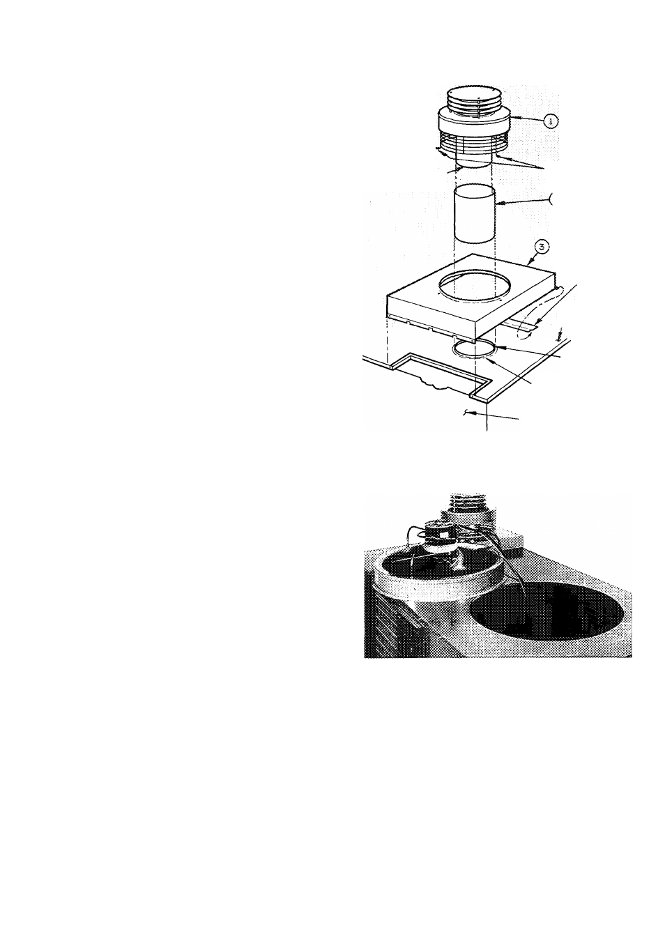
Assemble (Fig. 2)
1. Mount the combustion-air inlet box (item 3) by
sliding the horizontal box flange under the
retaining clip on the unit top cover. Fasten the
inlet box with sheet metal screws provided.
2. Place end of heat-shield collar and secure wind
cap assembly (item 1 ) with 3 sheet metal screws
thru wire cage eyelets.
PIPING AND WIRING
Gas Piping — Install piping per national and local
codes and ANSIZ223.1 entitled “National Fuel
Gas Code,” (published by American Gas Asso-
auEPiPc
(PARTOF WiNOCAP
ASS£M8LY)
WIND CAP
ASSSMSi-Y
EY£L£TS(3)
« yHSATrSHfEXP
‘^^COLtAR
COMBUSTfON
AiR
inlet
BOX
RETAININS
CUP
TOP
COVER
OF UNIT
!
TCP COVER
EXTRUSION
FLUE BOX
EXTRUSION
HEATING
SECTION
ACCESS PANEL
Fig. 2 — Wind Cap and Air Inlet Box Assembly
Fig. 3 — Removing Condenser Fan
and Orifice Assembly
ciation, 1515 Wilson Blvd., Arlington (Rosslyn),
VA 22209).
1. Furnish the gas line from the main gas supply
to the unit gas valve (Fig. 4). Connection at gas
valve is 1 /2 in. FPT.
2. Size the supply pipe for 0.3-in. wg maximum
pressure drop and for the volume of gas
required (Tables 2, 4 and 5). Pipe size must
equal or exceed size of gas connection at unit.
3. Use pipe dope approved for use with liquefied
petroleum (LP) gases.