Carrier 48EL User Manual
Page 6
Attention! The text in this document has been recognized automatically. To view the original document, you can use the "Original mode".
2. Set room thermostat selector switch at COOL
or AUTO, and dial setting below room
temperature.
3. Move thermostat dial above and below room
temperature several times, pausing at least 5
minutes between cycles. Check fan and com
pressor operation.
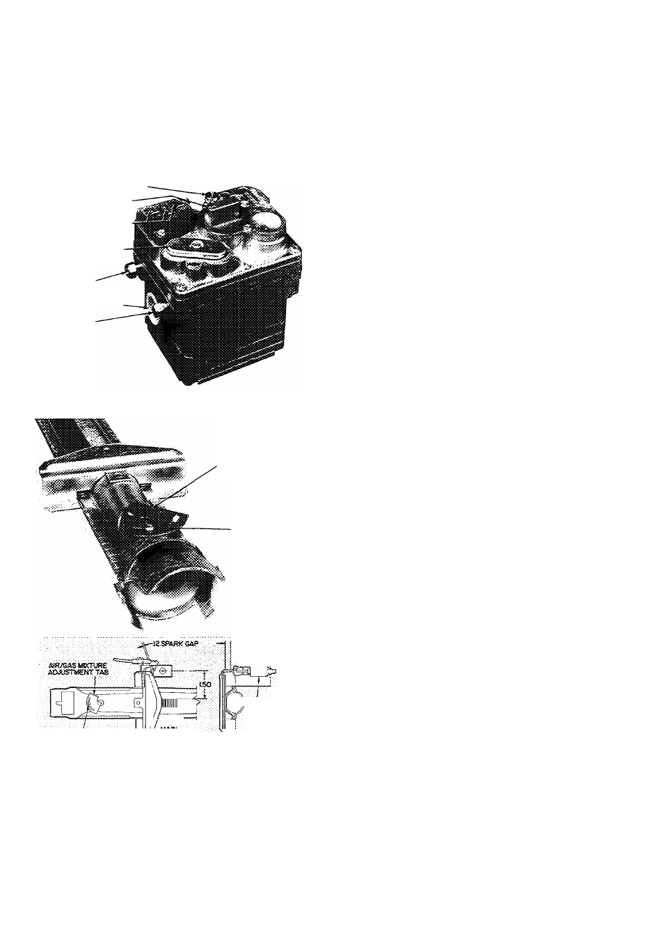
PILOT ADJUSTING SCREW CAP
MANUAL SHUTOFF VALVE
AND PILOT COCK
LOW VOLTAGE------------------
CONNECTIONS
REGULATOR ADJUSTING
COVER (ADJUST Hi"
SIDE SCREW)
PILOT GAS LINE
CONNECTION
MAIN GAS CONNECTION
PRESSURE TAP
Fig. 6 — Unit Gas Valve
AIR/GAS
MIXTURE
ADJUSTMENT TAB
LOCKING SCREW
-.33
^^.^eCTROOE
:«LOr SOOT
¡¡—T
LOCKING SCREW'
^
Fig. 7 — Main Burner Adjustment Details
Start-Up Sequence, Natural and LP Gas Units With
Intermittent Spark Ignition of Pilot, indoor (evap
orator) fan motor time delay relay and Essex
SX242 gas valve.
MANUAL SEQUENCE
1. With power off turn manual gas valve knob to
ON position.
2. Set thermostat selector switch at HEAT posi
tion and set thermostat dial a few degrees above
room temperature.
3. Turn power on, and unit automatically operates
as described below.
AUTOMATIC SEQUENCE
1. Pilot valve opens, spark ignition and indoor fan
time delay relay energize.
2.
Gas flows to pilot and ignites. Pilot flame
sensing probe permits energizing of the main
gas valve. Gas flows to main burner and ignites.
3. Time delay relay starts indoor fan motor in 30
— 45 seconds.
4. When thermostat setting is satisfied, main gas
valve and pilot gas valve close and flames are
extinguished.
5. Indoor fan motor stops in I - to 1-1/2 minutes.
CAUTION; l>o not use matches to li^t
pilof on iniennitient pilot units because of
electrical shock hazard-
GENERAL OPERATING SEQUENCES
These sequences apply to both natural and EP gas
units in normal operation after initial start-up.
Operating Sequence-Heating
NATURAE GAS AND LP UNITS WITH INTER
MITTENT PILOT
1. Thermostat selector switch at HEAT or AUTO.
Thermostat dial set above room temperature.
2. Pilot gas valve opens. Gas flows to pilot and
ignites. Pilot flame sensing probe causes main
gas valve to open. Gas flows to main burner and
ignites.
3.
TDR starts indoor fan motor in 30 — 45
seconds.
4. When thermostat is satisfied both pilot gas and
main gas valves close. Pilot and main burner
flames are extinguished.
5. TDR stops indoor fan motor in 1- to 1-1/2
minutes.
6.
Pilot is on only when thermostat calls for
heating.
Operating Sequence — Cooling
1. Unit energized. Thermostat selector switch at
COOL or AUTO. Thermostat dial set below
room temperature.
2. Indoor and outdoor fans and compressor start.
3. When thermostat setting is satisfied, fans and
compressor stop.
Automatic Operation — Power and gas on. Room
thermostat (control center) set at AUTO. Fan
switch (on control center) set at AUTO.
Unit performs as described in the operating
sequences above on call for heating or cooling.