Service, Table 5 — gas rate (cfm) – Carrier 48EL User Manual
Page 7
Attention! The text in this document has been recognized automatically. To view the original document, you can use the "Original mode".
Automatic changeover type thermostat is required.
Continuous Fan Operation — With power supplied
to unit and fan switch at ON position, indoor fan
remains on at all times.
Complete Shutdown or Change from Heating to
Cooling
1. Turn thermostat selector switch to OFF.
2. Remove heating section access panel.
3. Turn manual shutoff valve (Fig. 6) to PILOT.
Then depress valve and turn to OFF.
4. Turn off power. Replace access panel.
SERVICE
Adjusting Main Burner Gas Input (Refer to Fig. 4
and 6 and to Table 4 and 5) -- Need for adjustment
is determined by comparing measured gas input
(flow rate or manifold pressure) against the rated
input of a gas with a specific heating value. Check
local gas supplier for correct heating value (BTU’s
per cu ft). Before measuring, shut down all other
gas appliances.
Flow rate (cfm), the most accurate method, is
measured by gas meter and stop watch. Check
measured flow against rated flow in Table 5.
^
Table 5 — Gas Rate (cfm)
UNIT
48EL006
48EM006
Natural 1000
1 83
2 50
Natural 1050
1 74
2 38
Natural 1100
1 66
2 27
Butane 3200
57
78
Propane 2500
73
1 00
2
.
3.
4.
5.
6
.
Manifold pressure (in. wg) is measured as
follows:
1. Remove heating section access panel.
Shut down unit and close gas supply line valve
(Fig. 4).
Remove pressure tap plug from main gas valve
(Fig. 6) and install pressure tap.
Attach U-tube water gage manometer to pres
sure tap and open gas supply line valve.
Start-iip heating system.
Measure gas pressure (in. wg) and compare with
rated pressure in Table 4.
To adjust pressure or flow rate:
1. Remove pressure regulator adjusting screw cap
on main gas valve (Fig. 6).
Turn screw slowly, clockwise to increase pres
sure (flow), and counterclockwise to decrease.
Replace adjusting screw cap.
Shut down heating system.
Close gas supply line valve, remove manometer
and replace pressure tap plug.
Open gas supply line valve and replace heating
section access panel.
2
.
3.
4.
5.
6
.
Refrigerant Charging — Standard 1/4-in. Schrader
service connections are provided on the high and
low sides of the refrigerant system for charging and
evacuation.
Amount of refrigerant charge is listed on unit
nameplate (also refer to Table 1). Refer to Carrier
Standard Service Techniques Manual, Chapter 1,
Refrigerants.
Unit panels must be in place when unit is
operating during charging procedure.
NO CHARGE — Use standard evacuating tech
niques. After evacuating system, weigh in the
specified amount of refrigerant.
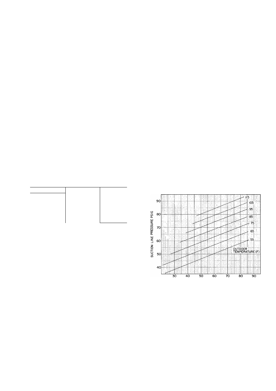
LOW CHARGE — Using charging chart (Fig. 8),
add refrigerant until the conditions of the chart
are met. Charts are based on charging the units to
the correct superheat for the various operating
conditions. An accurate pressure gage and tem
perature sensing device are required. Connect the
pressure gage to the service port on the suction
line. Mount the temperature sensing device on the
suction line and insulate it so that outdoor
ambient temperature does not affect the reading.
Indoor air cfm must be within the normal
operating range of the unit.
SUCTION LINE TEMPF
Fig. 8 — Charging Chart — 48EL,EM006
TO USE CHARGING CHART - Take the outdoor
ambient temperature and read the suction pressure
gage. Refer to chart to determine what the suction
temperature should be. If the suction temperature
is high, add refrigerant. If the suction temperature
is low, carefully blow some of the charge. Recheck
the suction pressure as charge is adjusted.
If Chargemaster® charging device is used, tem
perature and pressure readings must be accom
plished using charging chart. Fig. 8.