Carrier 38GK User Manual
Page 6
Attention! The text in this document has been recognized automatically. To view the original document, you can use the "Original mode".
8 Add charge by slowly opening Chargemaster®
valve. If necessary, reduce charge by bleeding at
liquid line service valve. Check outdoor air and
evaporator temperature during procedure. If
they change, refer back to Suction Line Tem
perature table for new value.
Correct use of Chargemaster ensures an opti
mum refrigerant charge will be in system when
conditions and system components are normal.
However, the Chargemaster does not solve or fix
system abnormalities. It indicates correct charge
for condition of system. It will not make correc
tions for dirty filters, slow fans, excessively long or
short suction lines or other abnonnal conditions.
This charging device ensures that a correct relation
ship exists between outdoor temperature, evapora
tor temperature, and suction line temperature on a
specific system.
Charging By Weight
— Remove any refrigerant
remaining in the system before recharging. A
Dial-a-Charge cylinder may be used to recharge the
system with reference to nameplate for correct
system charge.
SERVICE
Access to all controls and unit components is
thru rear access panel.
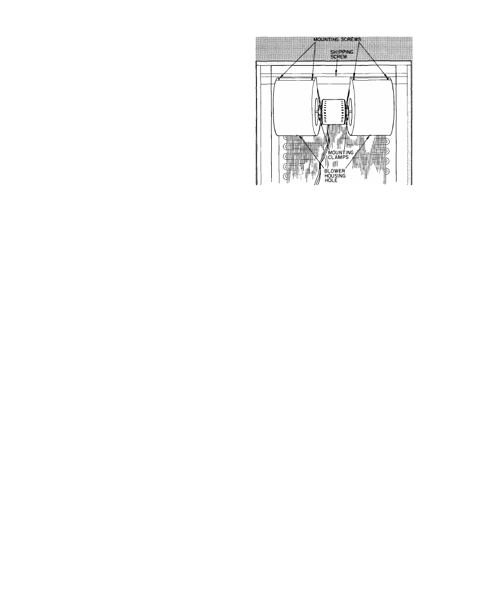
Blower Wheel and Motor Removal
— The blower
assembly may easily be removed thm the rear
access panel in the following manner’
1. Shut off all power to the unit.
2. Loosen and remove 3 screws holding the rear
access panel in place and remove the rear
access panel from the unit. See Fig. 5.
3. Disconnect the 2 electrical leads from the
blower motor to the compressor contactor.
4. Remove the 2 screws from the motor mount
ing clamps, the 4 mounting screws from the
blower housings and remove both housings
from the rear flange.
5. Insert a 3/8 x 9 in. long Allen wrench into the
hole at bottom of the blower housing.
6. Loosen and remove the setscrews on both
blower wheels and remove the wheels from the
shaft.
7 Lift out motor. Motor may be replaced at this
time, if necessary.
8. Place both wheels into each housing, and insert
motor shaft of motor thru housing and blower
wheel for proper wheel positioning.
9. Place blower housing onto the rear flange.
10. Start the 4 mounting screws of the blower
housing and align the blower motor between
the mounting brackets.
Fig. 5 — Rear Access Panel Removed
11. Place a brace between the blower motor and
the compressor to support the motor.
12. Attach the rear clamp, first, then the front
clamp to the motor mounting brackets before
tightening the clamp screws.
13. Rotate the blower wheel until the bottom
holes of the blower housing, the large hole in
the blower wheel, and the Allen setscrews are
aligned.
14. Adjust and tighten the blower wheels in
position on the motor shaft, using the Allen
wrench.
15. Tighten the 4 mounting screws of the blower
housing.
16. Connect the 2 electrical leads from the blower
to the compressor contactor. Make sure both
speed taps of the motor are not energized at
the same time.
17. Replace the rear access panel and tighten the 3
screws.
18. Turn on power to unit.
38GK Unit Single-Phase Compressors
of the split
capacitor (PSC) type require an equalized system
pressure to start. (Equalization takes approxi
mately 3 minutes.) When supply voltage is within
permissible limits and compressor does not start,
give compressor a temporary capacitance boost.
See Carrier Standard Service Techniques Manual,
Chapter 2, for details. Use a 130 mfd start
capacitor. Run compressor for 10 minutes, then
shut off and allow system pressure to equalize. Try
restarting without boost capacitor. If after 2
attempts (without boost capacitor) the compressor
does not start, add an accessory start capacitor
relay package.