Carrier 38GK User Manual
Page 2
Attention! The text in this document has been recognized automatically. To view the original document, you can use the "Original mode".
INSTALLATION
Mounting Thru-The-Wall
An opening approximately 26-1/2 x 29 in. shall
be made in a wall as close to a nearby cooling coil
as possible. Refer to Fig. 2 to build a frame in a
manner to support the condensing unit.
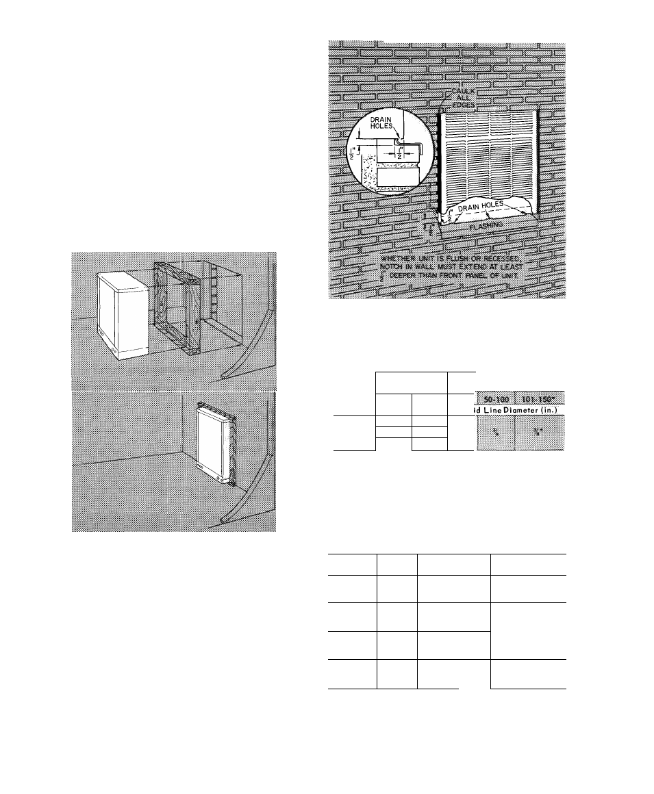
1. Locate unit with frame into the opening until
the unit extends approximately 1 in. beyond
the outside (finished) wall.
Tilt to the front to allow the water to drain off.
See Fig. 3.
Fasten the unit to the frame with metal straps.
Use flashing under the unit and caulk all edges
to provide a weathertight seal (Fig. 3).
2
.
3.
4.
Fig. 2 — Roughing-ln Supporting Frame
REFRIGERANT LINE SIZING
Selection of Correct Liquid Line
— See Table 3 for
maximum allowable vertical and horizontal dis
tance between condensing unit and evaporator
using recommended 3/8-in. liquid line.
Selection of the Correct Suction Line Diameter —
To keep line losses at a minimum, refer to Table 4
to select the correct suction line diameters.
Fig. 3 — Flush or Recess Mounting
Table 3 — Recommended Liquid Line Sizes
COND
MAX COND*
UNIT HT (ft)
REFF
UNIT
Above
Below
0-49
Evap
Evap
Liqu
38GK001
40
50
38GK002
40
70
%
38GK003
40
60
Crankcase heater required
*Decrease maximum allowable vertical separation by 20% for
every 10 ft of refrigerant line length over 100 feet At 150 ft of
line length, 0 ft vertical separation is allowed
Table 4 — Recommended Suction Line Diameters
UNIT
MODEL
SUCTION LINE
LENGTH (ft)
SUCTION
LINE
DIAMETER (in.)
0
46
=/
b
38GK001
(All)
47 - 120
%
121 - 150
V
b
*
0 -
28
%
38GK002
(All)
29 -
72
V
b
73 - 150
V
b
*
0 -
19
V
/4
38GK003
201
20 -
52
V
'A
53 - 116
7/*
0 -
18
%
38GK003
301
19 -
48
%
49 - 107
V
b
*
*Field-supplied 7/8-in to 3/4-in adapter is required
NOTE
The above table is based on a line loss of 2 F Longer lengths can
be used in each diameter listed, but the result will be larger line
losses Refer to Carrier, Syracuse Engineering Office for specific
details