Comti^tes ainm 813.4 h not hy omor, Wsrrsniy – Carrier 38GK User Manual
Page 4
Attention! The text in this document has been recognized automatically. To view the original document, you can use the "Original mode".
4. Pressurize the system with refrigerant to 10 psig
and backseat (turn counterclockwise) both
service valves.
5. Remove the refrigerant cylinder. Replace the
valve stem and service port caps on both service
valves (be sure they are tight) if system is to be
left in purged condition.
ELECTRICAL DATA AND WIRING
Table 5 — Electrical Data
COND
UNIT
001
002
003
V/PH
208TÌ'
2
’
30
/i
208/1
230/1
208/1
230/1
OPER*
VOLTS
Max
229
253
229
253
229
Min
8/”
207
COMPR
L R A
60 0
51 0
1
T
2
'
11
0
FAN
BRANCH CIRCUIT
i rusei
Wire F
mo
X :
re
Si zet
F f t
FLA (AWG)iWire
Amps
1 9
174 0 115 5 1
8/
S0,b|15,? ,
!o I
0
113
.
6 I
20/'
72,0 14J I
1.94.0 1/0.5
Í 12
1 37
25
i 12
1 44
25
: in
1 /Iß
llili
'2
i 3d
1 12 1 37
30
liiii
A
33
■ 10
45
iiiii
253 1207
Electrical data for unit models with 06M compressor
FLA — Full Load Amps
LRA — Locked Rotor Amps
‘Permissible limits of the voltage range at which the units will oper
ate satisfactorily
/Copper wire sizes and lengths. Use latest National Electrical Code
(NEC) for aluminum wire sizes
/Maximum dual element fuse size
NOTES:
1 Control circuit voltage is 24 volts on all units
2 Aluminum field wiring may be used
Wiring
— Field wiring must comply with local and
national fire, safety and electrical codes. Voltage to
unit must be within ± 10% of voltage indicated on
nameplate. Contact local power company for
correction of improper line voltage. ^
of
tim t tm
litie voltaic
coMti^tes ainm 813.4 h not
hy Omor
Wsrrsniy,
See Table 5 for recommended wire and fuse
size. When making electrical connections, provide
clearance at unit for refrigerant piping connections.
INSTALL A BRANCH CIRCUIT FUSED DIS
CONNECT of adequate size to handle unit starting
current. Locate disconnect within sight of and
readily accessible to the unit, per section 440-14 of
National Electrical Code (NEC).
BRING LINE POWER LEADS INTO UNIT -
Extend leads from fused disconnect into unit thru
hole provided in service panel, Eig. 1 Connect
ground lead to ground lug in control box for
safety. Connect line power leads to contactor
screw terminals LI and L2. See Fig. 4. Contactor
terminals are approved for use with copper or
aluminum field wiring.
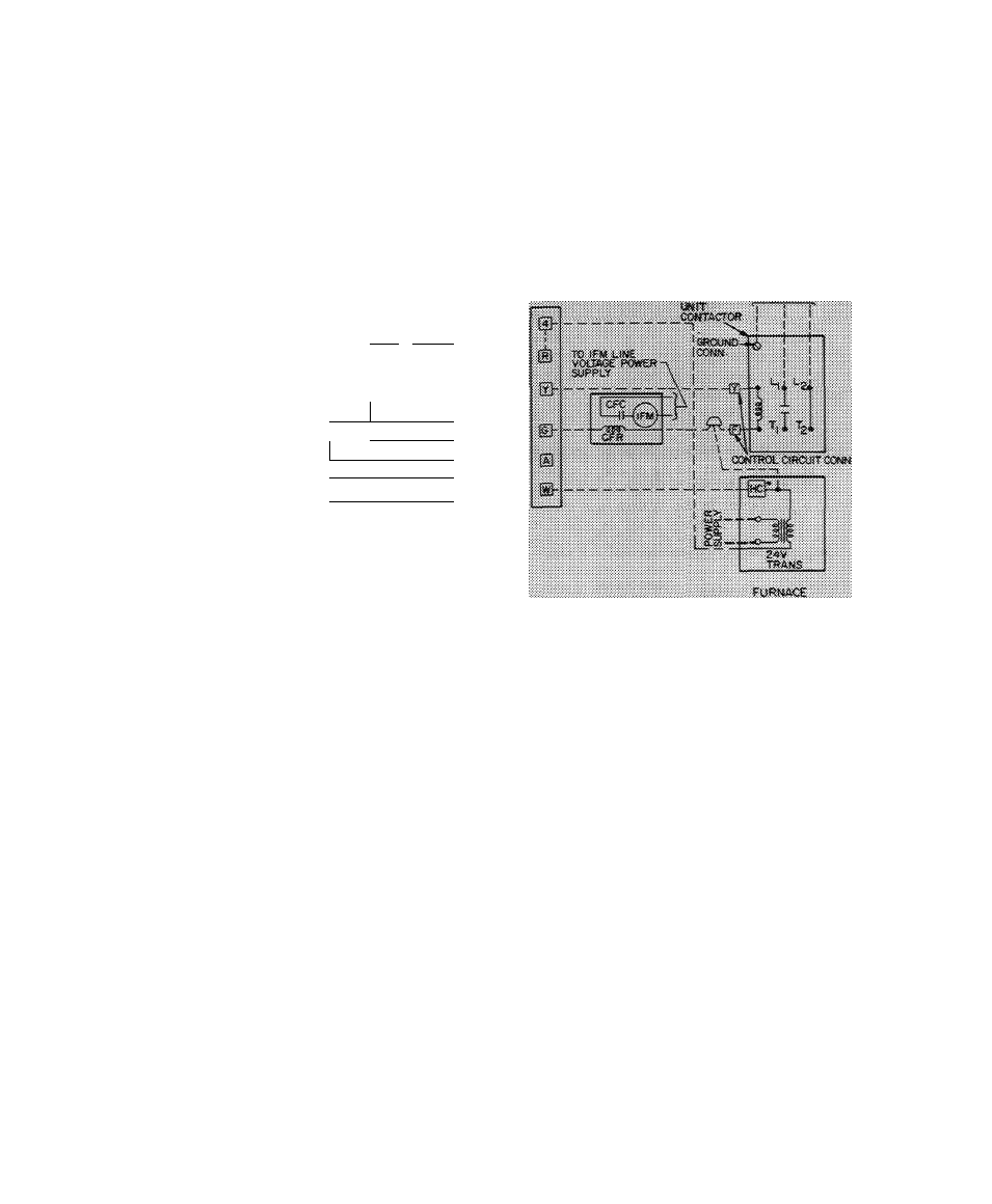
CONTROL POWER (24 v) — Use furnace or
fan-coil transformer as 24-v supply for system
Transformer must have a minimum capacity of 30
va. Bring control wiring thru hole in unit service
panel and connect to pigtails from unit contactor.
Contactor pigtails are labeled Y and F. Refer to
Fig. 4 for system control circuit connections.
CFC *- C/4
,f>i<
----------
r j - í V i C - . í
-
-i'-x
im
- ¡l’-i'-riiS r.íí '/(/"/>
<'''>».' w
w'......... . - w /
/,(. ■' ■' / !!'<■' I'.-i
''-i'
.
> Fig. 4 — Control Circuit Connections
^
START-UP
Energize crankcase heater (if so equipped) a
minimum of 24 hours before starting unit. To
energize heater only, turn the thermostat to “Off”
position and close electrical disconnect to con
densing unit.
Start Procedure
1. Backseat (open) liquid and suction line service
valves.
2. Set thermostat selector switch at “Off.”
3. Set room thermostat to desired temperature.
4.
Close electrical disconnects energizing entire
system.
5. Set room thermostat at “Cool” and fan switch
as desired (“Ean”) (“Auto.”). Operate unit for
15 minutes, then check system refrigerant
charge. See Refrigerant Charging.
r