Automatic electric drain valves, Zero air loss condensation drain – Wilkerson F37 User Manual
Page 2
Automatic Electric Drain Valves
Model
Number Kit
Port Size
NPT
Voltage
Operating
Pressure
WDV3-G14BL
1/2"
115 VAC
232 PSIG
WDV3-G24BL
1/2"
230 VAC
232 PSIG
WDV3-G34BL
1/2"
24 VDC
232 PSIG
Zero Air Loss Condensation Drain
Model
Number Kit
Port Size
NPT
Voltage
Operating
Pressure
ED3002N115-KL
1 x 3/8, 3/8
115 VAC
232 PSIG
ED3004N115-KL
1 x 1/2, 3/8
115 VAC
232 PSIG
ED3007N115-KL
2 x 1/2, 3/8
115 VAC
232 PSIG
ED3030N115-KL
2 x 1/2, 3/8
115 VAC
232 PSIG
ED3100N115-KL
2 x 1/2, 3/8
115 VAC
232 PSIG
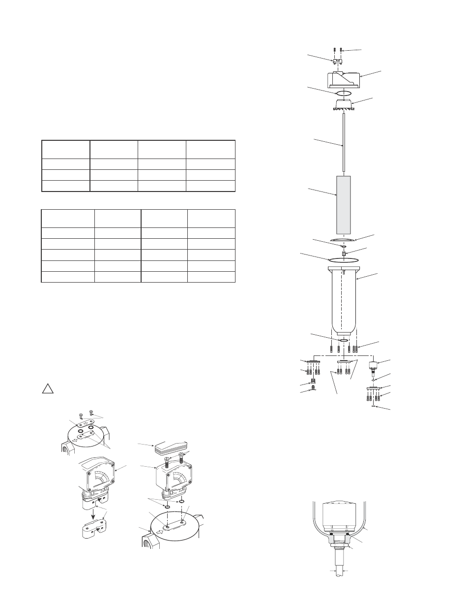
Nut
Bowl
O-ring
Use 3/8"
or 10mm
Flex Tubing
Differential
Pressure
Indicator
Deflector
Vane
5 Micron
Element
Nut
(Torque 50 ± 5 lb-in)
O-ring
Gasket
Cover
NNR
Stud
Baffle
Metal
Bowl NNR
Screw (2 Required)
(Torque 12 ± 2 lb-in)
Drain Plate
Screws (6 Required)
(Torque 4 ± 1 lb-in)
O-ring
O-ring
Screws (8 Required)
(Torque 18 ± 4 ft-lb)
Automatic
Mechanical
Drain (Optional)
Drain Plate
Nut (For Auto Drain)
Screws (6 Required)
(Torque 4 ± 1 ft-lb)
O-ring
Drain Plate
Drain Cock
Pipe Bushing
Screws (6 Required)
(Torque 4 ± 1 ft-lb)
Filter Models F35, F36, F37 and F43 with Variations and Accessories
83-719-000
F35 / F36 / F37 / F43
DP3 Differential Pressure Gauge Installation
Instructions on 3x / 4x Series Filters
1. Remove and discard the plastic cap, screws and O-rings from top of
unit.
2. To install the new DP3 Differential Pressure Gauge, pry the cap
out of the housing and separate the mounting block from the DP3
by removing the 2 screws under the cap. Make sure that air flow
direction arrows on DP3 match flow arrows (same direction) on filter
unit. Make sure O-Rings are properly seated on bottom of DP3, and
attach DP3 to filter, using the special 60mm mounting screws
(2 required) with flat ground on threads.
CAUTION! Overtightening the screws may damage the
Differential Pressure Gauge. Recommended torque for
screws is 36 in-lbs.
!
Automatic Mechanical Float Drain
Repair Kits And Replacement Parts (continued)
Internal Drains:
Automatic Mechanical Drain:
(Fluorocarbon seals w/ 1/8 NPT stem) ............................GRP-95-981
Automatic Mechanical Drain:
(Fluorocarbon seals w/ R1/8 stem)..................................GRP-96-300
Manual Override for Auto Drain:
(GRP-95-981) NPT Body Threads...................................GRP-96-001
(GRP-96-981) BSPP-G Body Threads ............................GRP-96-101
External Drains:
External Automatic Mechanical Drain ............................... X01-04-000
External Automatic Mechanical Drain ...............................X02-04-F00
External Automatic Mechanical Drain ...............................XB3-04-000
* CAUTION: Use special 60 mm (long) screw to mount gauge to
filter only.
3. Replace coalescing element when differential pressure reaches
the
red band.
Plastic Cap
O-Rings
Remove
and
Discard
Mounting
Block
O-Rings
Inlet
Port
Outlet
Port
Filter
DP3
Housing
Cap
(snaps into
housing)
Screws
(2 Required 12 ± 2 lb-in)
Special Screws
*
(2 ea. included)
60 mm with flat
ground on threads
(torque 36 ± 2 lb-in)