Particulate filter (figure 2) description, Installation of filter, Service kits - lubricator – Wilkerson 1M103G User Manual
Page 2: Parts identification list - lubricator, Service kits- filter, Operation of the filter, Service, Servicing filter element, Parts identification list - filter units
Micro-Mist Lubricator & Particulate Filters Series
1M103G
Particulate Filter (Figure 2)
Description
These air line filters are heavy-duty units used to remove airborne impurities from
air supply lines by means of centrifugal force and filter element. Units are equipped
with vane-type deflectors and drain valves. Deflector plate creates swirling action to
the air stream assuring entrainments separation at all flow rates. Filter element with
extra large surface assures fine filtration with low pressure drop. Turn manual drain
counterclockwise to open and clockwise to close.
Installation of Filter
1. Filter should be installed with reasonable accessibility for service whenever possible
- repair service kits are available. Keep pipe and tubing lengths to a minimum
with inside clean and free of dirt and chips. Pipe joint compounds should be used
sparingly and applied only to the male pipe - never into the female port. Do not use
PTFE tape to seal pipe joints - pieces have a tendency to break off and lodge inside
the unit, possibly causing malfunction.
2. Install unit so that air flow is in the direction of arrow. Installation must be upstream of
and close to devices it is to service (valve, cylinder, tool, etc.). Position unit vertically
with the bowl drain mechanism at the bottom. Free moisture will thus drain into the
sump (“quiet zone”) at the bottom of the bowl.
25
20
19
22
21
23
20
24
33
27
26
Torque Bowl to
bottom stop, then
back off Bowl 22
to 45
TORQUE:
finger tight
TORQUE:
8 - 12 in-lbs
29
30
31
26
28
TORQUE:
1 - 3 in-lbs
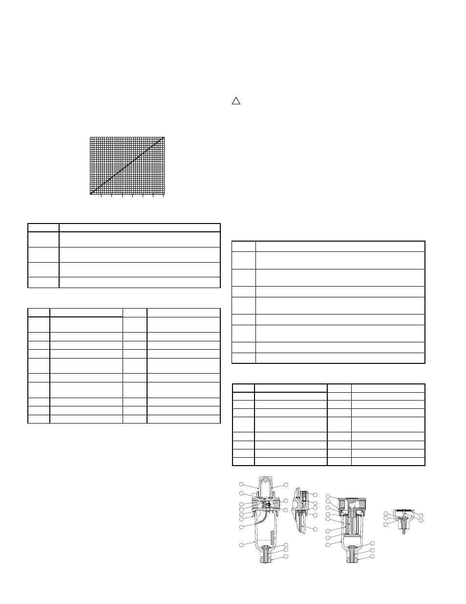
Figure 1: Micro-Mist Lubricator
Figure 2: Particulate Filter
19
7
2
3
4
5
6
1
8
18
13
12
11
10
9
17
16
15
14
Torque Bowl to
bottom stop, then
back off Bowl 22
to 45
TORQUE:
finger tight
TORQUE:
10-15 in-lbs
3. OIL DELIVERY ADJUSTMENT - To adjust oil delivery, turn the adjusting needle on
top of the lubricator.
Leaner - Clockwise Richer - Counterclockwise
By counting the number of drops per minute in the sight dome, you can adjust lubricator
to your required setting. Approximately 3% of the droplets visible in the sight dome
go downstream; adjust drip rate accordingly. Consult oil delivery conversion chart
(see below).
Generally, one drop per minute downstream for every 10-15 SCFM flow is satisfactory.
25 drops per minute equals one ounce per hour - volume of oil passing through the
sight dome.
NOTE:
This is a constant density type lubricator which delivers a constant ratio of oil to
air flow. Therefore, if air flow increases or decreases, oil delivery will be effected
proportionately. ONLY IF DIFFERENT RATIO IS DESIRED NEED YOUR NEEDLE
VALVE SETTING BE CHANGED AFTER YOUR INITIAL SETTING.
1
2
3
4
5
6
7
Downstream Delivery DPM
33
67
100
133
167
200
233
Dome Drip Rate DPM
Oil Delivery Conversion
3% of Drip Rate to Downstream
Service Kits - Lubricator
Kit#
Description
PS420
Polycarbonate Bowl with Manual Drain - consists of items: 1 (open
bottom), 4, 12 & 13
PS421
Polycarbonate Bowl without Drain - consists of items: 1 (closed
bottom) & 4
PS447B
Metal Bowl with Manual Drain - consists of items: 1 (open bottom),
4, 12 & 13
P05117
Twist Drain Knob
Parts Identification List - Lubricator
Item#
Description
Item#
Description
1
Bowl - open & closed
bottoms (open shown)
11
Restrictor
2
Deflector
12
O-ring (drain to bowl)
3
Body
13
Manual drain (twist style)
4
O-ring (body to bowl)
14
Metering screw
5
Eyelet
15
O-ring (metering screw
to body)
6
Atomizer
16
Seal (deflector to body)
7
Gasket (body to inner &
outer sight domes)
17
Check ball
8
Outer sight dome
18
Pickup tube
9
Inner sight dome
19
Twist Drain knob
10
Eyelet
Service Kits- Filter
Kit#
Description
PS404
Polycarbonate Bowl with Manual Drain -
consists of items: 19, 24, 26 & 27
PS408
Polycarbonate Bowl with Automatic Drain -
consists of items: 19, 24, 26, 28, 29, 30, 31 & 32
PS447B
Metal Bowl with Manual Drain - consists of items: 19, 24, 26 & 27
PS451
Metal Bowl with Automatic Drain -
consists of items: 19, 24, 26, 28, 29, 30, 31 & 32
PS403
5 Micrometer Element Kit - consists of items: 20, 21 & 24
PS407
5 Micrometer Element Cartridge Kit -
consists of items: 20, 21, 22, 23 & 24
PS401
40 Micrometer Element Kit - consists of items: 20, 21 & 24
P05117
Twist Drain Knob
Operation of the Filter
1. Both free moisture and solids are removed automatically by the filter.
2. Manual drain filters must be drained regularly before the separated moisture and
oil reaches the bottom of the element holder. Automatic drain models (pulse drain)
will collect and dump liquids automatically. They are actuated when a pressure drop
occurs within the filter.
3. The filter element should be removed and replaced when the pressure differential
across the filter exceeds 70 kPa (10 psig, 0.7 bar).
Service
Caution: SHUT OFF AIR SUPPLY and exhaust the primary and secondary
pressure before dis-assembling unit. (Units may be serviced without
removing them from the air line.)
Servicing Filter Element
1. Unscrew threaded bowl and element holder. Then remove filter element, deflector,
and gaskets.
2. Clean all internal parts, bowl, and body before re-assembling unit. See Polycarbonate
bowl cleaning section.
3. Install deflector, filter element, and gaskets.
4. Attach element holder. Torque from 0.9 to 1.4 N•m (8 to 12 in-lbs).
5. To assist with retaining bowl’s o-ring while installing bowl, lubricate the o-ring (with
a mineral based oil or grease). Then place on the bowl.
6. Screw bowl into the body until it is stopped by body; then back off bowl 1/8 turn.
7. Apply pressure to the system and check for leaks. If leaks occur, shut off the air
supply, de-pressurize the system and make necessary adjustments to eliminate
leakage.
If you have questions concerning how to service this unit, contact your local dealer or
your customer service representative.
!
Parts Identification List - Filter Units
Item#
Description
Item#
Description
19
Bowl
27
Manual Drain (twist style)
20
Gasket
28
Brass Barbed Fitting
21
Filter Element
29
O-ring - pulse drain
22
Filter Holder
30
Drain (body of pulse drain
shown))
23
Deflector
31
Diaphragm
24
O-ring (body to bowl)
32
Pin
25
Body
33
Twist Drain Knob
26
O-ring (drain to bowl)