Connector pipe installation, Locating stove continued – Vogelzang VG450ELGB User Manual
Page 6
Page 6
/
VG450EL FrontiErsman™
www.vogelzang.com
VGZ-014 / 20120424.0
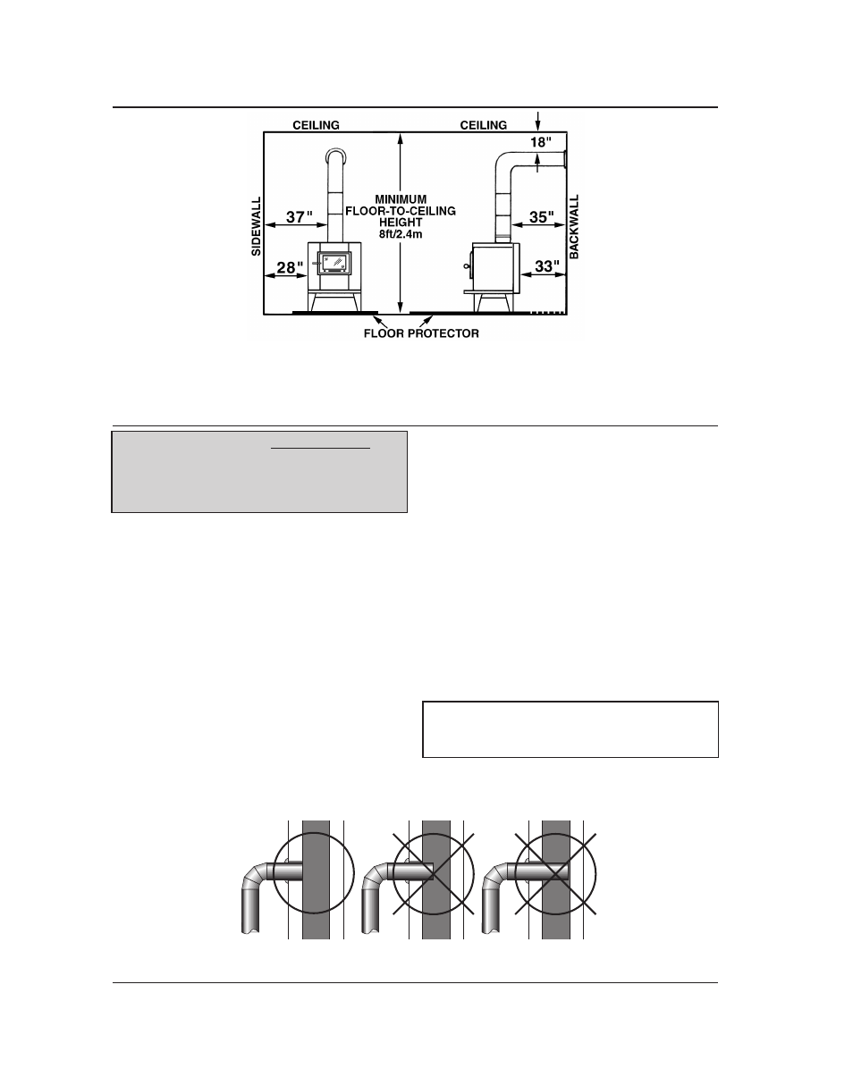
Fig. 3a – FrONT VIEw
Minimum Clearance Dimensions
from Combustible Surfaces
Fig. 3b – SIDE VIEw
Minimum Clearance Dimensions
from Combustible Surfaces
CONNECTOR PIPE INSTAllATION
1. The straight end of the stovepipe fits over the
stove flue collar. Secure with three (3) sheet
metal screws.
2. Horizontal pipe runs must slope upwards
towards the chimney at least 1/4” per foot of
horizontal run. This allows any condensation
in the pipe to drain back into the firebox.
3. You must have at least 18 inches of clearance
between any horizontal piping and the ceiling.
4. The pipe cannot extend into the chimney flue
(figure 4).
5. Secure the pipe/flue collar and all pipe/elbow
sections with three (3) sheet metal screws at
each joint to make the piping rigid. Screws
may be no more than a maximum of 3˝/76mm
apart.
6. It is recommended that no more than two (2)
90° bends be used in the stovepipe installa-
tion. The use of more than two 90° bends may
decrease the amount of draw and possibly
cause smoke spillage. Where possible, use only
corrugated (nonadjustable) elbows. These
provide a better seal.
7. The connector pipe must not pass through an
attic or roof space, closet, or any concealed
space, or floor, ceiling, wall or combustible
construction. (See Chimney Connector Sys-
tems & Clearances, page 10). A manufactrured
chimney system listed to UL 103 HT must
be used from the first penetration of ceiling or
wall to the chimney cap. Any wall or ceiling
penetrations must conform to NFPA 211.
Fig. 4 – Stovepipe/Flue Connections
COrreCT
wrOnG wrOnG
nOTe: sTOVe PIPe Is NOT INClUDED. TO
PurChase, VIsIT YOur lOCal harD-
ware, hOMe Or BuIlDInG CenTer. see
“lOCaTInG sTOVe” PaGe 3 FOr aDDITIOnal
sPeCIFICaTIOns.
lOCATINg STOvE continued…
warnInG: DO nOT use sInGle wall COn-
neCTOr PIPe as a ChIMneY - a hOuse FIre
COulD resulT.