Viconics VTR7300 Application Manual User Manual
Page 18
18
Programming and status display instructions
Status display
The VTR73xxA Terminal Equipment Controller features a two-line, eight-character display. There is a low-level backlight
level that is always active and can only be seen at night.
When left unattended, the Terminal Equipment Controller has an auto scrolling display that shows the actual status of
the system. There is an option in the configuration menu to lockout the scrolling display and to only present the room
temperature and conditional outdoor temperature to the user. With this option enabled, no local status is given of mode,
occupancy and relative humidity.
Each item is scrolled one by one with the back lighting in low level mode. Pressing any key will cause the back light to
come on to high level. When left unattended for 10 seconds after changes are made, the display will resume automatic
status display scrolling.
To turn on the back light to high level, press any key on the front panel. The back lit display will return to low level when
the Terminal Equipment Controller is left unattended for 45 seconds
Sequence of auto-scroll status display:
Room & Humidity
System Mode
Schedule Status
Outdoor Temperature
Alarms
x.x °C or °F
Sys mode
Occupied
Outdoor
Service
XX % RH
Auto
x.x °C or°F
If humidity display
enabled
Sys mode
Cool
Stand-By
Network value only
Filter
RoomTemp
x.x °C or °F
Sys mode
heat
Unoccup
Window
If humidity display is not
enabled
Sys mode
off
Override
Low
Batt
% RH display is conditional to:
(Humidity display is model and configuration dependent)
• Model with RH sensor built in
•
Display function can be enabled with RH display parameter. Displayed range is 10 to 90 % RH
Outdoor air temperature
•
Display is only enabled when outdoor air temperature network variable is received.
Occupancy Status
•
Occupied, Stand-By, Unoccupied and Override status are displayed on the scrolling display.
Alarms
• If alarms are detected, they will automatically be displayed at the end of the status display scroll.
• During an alarm message display, the backlit screen will light up at the same time as the message and shut off
during the rest of the status display.
•
Two alarms maximum can appear at any given time. The priority for the alarms is as follows:
Service
Indicates that there is a service alarm as per one of the programmable binary input ( BI2 )
Filter
Indicates that the filters are dirty as per one of the programmable binary input ( BI2 )
Window
Indicates that the outside window or door is opened and that the Terminal Equipment Controller has
cancelled any cooling or heating action ( BI1 )
Low Batt
Indicates that attached wireless switching devices ( Door or window contact ) have a low battery condition.
Only functional when used with a wireless communication adapter
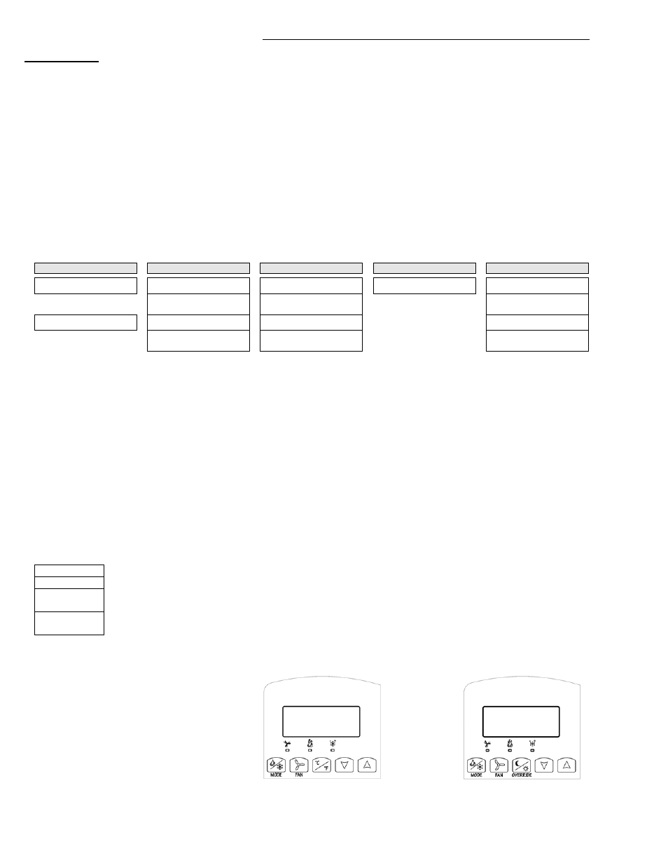
Three status LED’s on the Terminal Equipment Controller cover are used to indicate the status of the fan ( any speed ), a call for
heat, or a call for cooling.
Fan coil models
•
When any of the fan speeds are ON,
the FAN LED will illuminate.
•
When heating & reheat is ON,
the HEAT LED will illuminate.
•
When cooling is ON,
the COOL LED will illuminate.
Fig.11 – Hotel models °C/°F
Fig. 12 Commercial models with Override