Notice – VACUUBRAND PC 620 NT plastic housing User Manual
Page 38
page 38 of 113
Condensate and deposits will affect the measurement re-
sults. Clean the pressure transducer, if necessary. See
section “Cleaning the pressure transducer”, pg. 72.
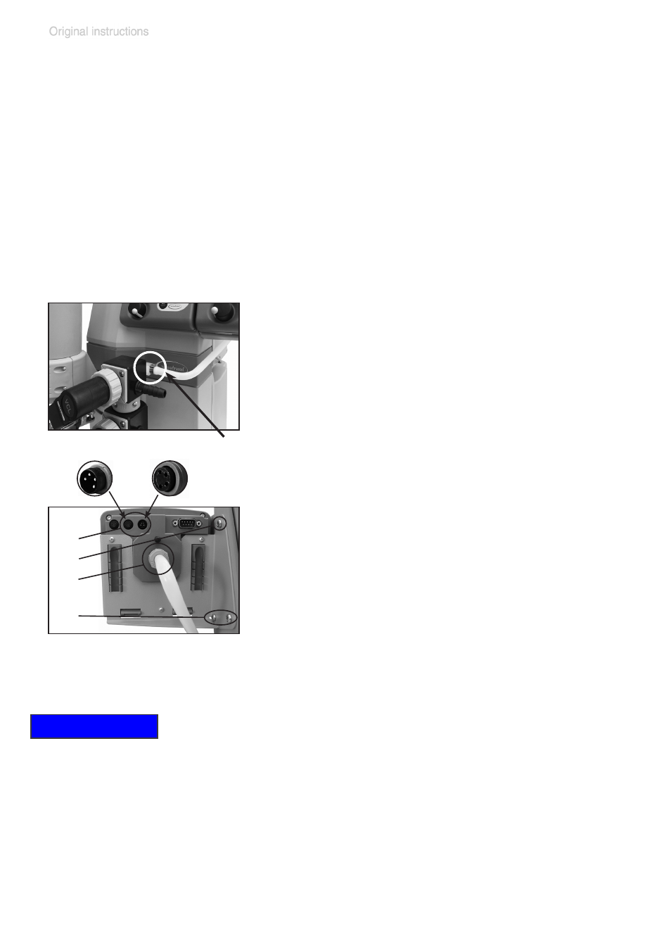
Assembling the second CVC 3000 controller
(only PC 520 NT / PC 620 NT):
The pumping unit’s second CVC 3000 controller controls
the in-line valve at the second inlet (upper vacuum con-
nection). Mount the controller prior to operating the pump-
ing unit.
➨
Affix the controller with its holding plate to
the pumping unit (three Allen screws (f), 2.5
mm wide Allen key). Install the washers and
screw the holding plate into position.
➨
Slip the enclosed molded PTFE hose onto
the hose connection of the valve block at
the inlet (a). Fasten with hose clip. Close
hose clip with flat pliers.
➨
Slip the other end of the PTFE hose onto
the vacuum connection (c) of the CVC 3000
and fasten with union nut.
➨
Plug in the VACUU•BUS lines at the rear of
the controller (b): Power supply line of the
controller (d) and control line of the in-line
valve (e).
Attention: Do not apply off-axis forces when
assembling or removing plug connections!
Observe correct orientation of the plug.
Carrying the pumping units:
Hold the pumping unit with one hand at its handle and tilt
it slightly backwards.
Reach with the other hand underneath the pumping unit
and lift the pumping unit.
Or: Use the recessed grips on the side of the pump (below
pump heads). Do not grab if the pump is hot.
Attention: Do not grab the pumping unit at the holders of
the waste vapor condenser or of the catchpot!
(b)
(f)
(c)
(f)
(d)
(e)
(a)
NOTICE