Checking the ultimate vacuum – VACUUBRAND PC 620 NT plastic housing User Manual
Page 104
page 104 of 113
➨
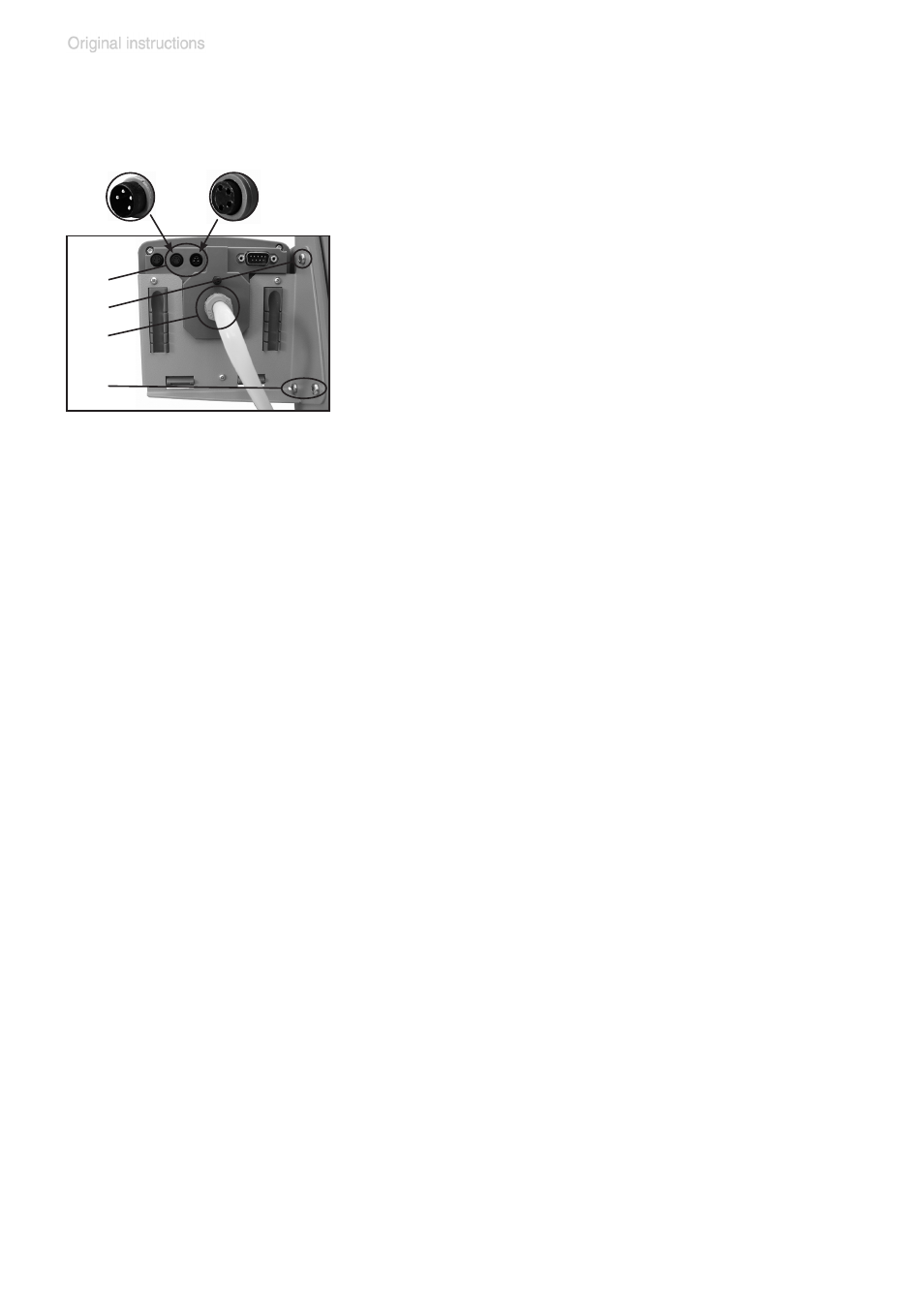
Affix the controller with its holding plate to
the pumping unit (three Allen screws (f), 2.5
mm wide Allen key). Install the washers and
screw the holding plate into position.
➨
Slip the loose end of the PTFE hose onto
the vacuum connection (c) of the CVC 3000
and fasten with union nut.
➨
Plug in the VACUU•BUS lines at the rear of
the controller (b): Power supply line of the
controller (d) and control line of the in-line
valve (e).
Attention: Do not apply off-axis forces when
assembling or removing plug connections!
Observe correct orientation of the plug.
(b)
(f)
(c)
(f)
(d)
(e)
Assembling the second CVC 3000 controller
(only PC 520 NT / PC 620 NT):
If the pump does not achieve the ultimate vacuum:
- Whenever the diaphragms and valves have been replaced, a break-in
period of several hours is required before the pump achieves its ulti-
mate vacuum.
- In case of an unusual noise, switch off pump immediately and check
clamping disc positions.
If the specified ultimate vacuum is not achieved, and if this does not
change after the break-in period:
Check hose connectors at pump heads for leaks. If necessary recheck
valve seats and pump chambers.
Checking the ultimate vacuum
➨
After any intervention at the equipment (e.g., repair / maintenance)
the ultimate vacuum of the pump has to be checked. Only if the pump
achieves its specified ultimate vacuum, the pump’s leak rate is low
enough to ensure that no explosive atmospheres will occur in the inte-
rior of the equipment.
After any intervention at the vacuum sensor the leak rate of the equip-
ment has to be checked.